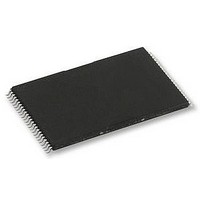
H27UAG8T2ATR-BC HYNIX SEMICONDUCTOR, H27UAG8T2ATR-BC Datasheet - Page 52

H27UAG8T2ATR-BC
Manufacturer Part Number
H27UAG8T2ATR-BC
Description
58T1891
Manufacturer
HYNIX SEMICONDUCTOR
Datasheet
1.H27UAG8T2ATR-BC.pdf
(61 pages)
Specifications of H27UAG8T2ATR-BC
Memory Type
Flash - NAND
Memory Size
16Gbit
Memory Configuration
2048M X 8
Supply Voltage Range
2.7V To 3.6V
Memory Case Style
TSOP
No. Of Pins
48
Operating Temperature Range
0°C To +70°C
Rohs Compliant
Yes
Available stocks
Company
Part Number
Manufacturer
Quantity
Price
Company:
Part Number:
H27UAG8T2ATR-BC
Manufacturer:
HYNIX
Quantity:
2 526
Company:
Part Number:
H27UAG8T2ATR-BC
Manufacturer:
SIEMENS
Quantity:
390
Company:
Part Number:
H27UAG8T2ATR-BC
Manufacturer:
HYNIX
Quantity:
4 000
Part Number:
H27UAG8T2ATR-BC
Manufacturer:
HYNIX/海力士
Quantity:
20 000
Rev 1.0 / Aug. 2010
5. INTERLEAVED OPERATION
Interleaving operations improve the system throughput compared to non-interleaving operations. In the stacked
device sharing a common CE# pin, interleaved operation is available. When both chip are ready state, input a com-
mand to the chip #1. And then, while chip #1 is busy state, issue a command to the other chip. When performing
interleaved operations, the operations shall be the same type. The functions that may be used in the interleaved oper-
ations are Page Read, Page Program, Block Erase, Multi Plane Page Read, Multi Plane Page Program, and Multi Plane
Block Erase. During interleaved operations, 70h command is prohibited exceptionally. Each chip status can be checked
by Multi Plane Read Status Command (78h). The R/B# pin shows when both chip are Ready or Busy. While either chip
is busy, R/B# pin is low. All chips are Ready state and interleaved operations are complete, R/B# pin goes high. Cache
function and Copyback function are impossible for interleaved operation.
5.1. Interleaved Page Read
Figure 51 shows how to perform interleaved PAGE READ operations. In Figure, the status register is monitored for
operation completion with the Multi plane status read (78h) command. When the host has issued Page Read com-
mands to multiple die at the same time, the host shall issue Multi plane status read (78h) command before reading
data from either die. This ensures that only the die selected by the 78h command responds to a data output cycle after
being put in data output mode with a 00h command, and thus avoiding bus contention. The host can use 78h com-
mands to read out data from another die.
Note:
70h command is prohibited during interleaved operations.
5.2. Interleaved Multi Plane Page Read
Figure 52 shows how to perform interleaved Multi Plane Page Read operations using the Multi plane read status (78h)
command to monitor the status register for operation completion. When the host has issued Multi Plane Page Read
commands to multiple die at the same time, the host shall issue Multi plane read status (78h) command before read-
ing data from either die. This ensures that only the die selected by the 78h command responds to a data output cycle
after being put in data output mode with a 00h command and 5 address cycles, and thus avoiding bus contention. The
interleaved Multi plane page read operation must meet two-plane addressing requirements.
■
I/Ox
R/B#
(chip 1 internal)
R/B#
(chip 2 internal)
R/B#
(external)
Figure 51. Interleaved page read
00h
Address
(5cycle)
Chip 1
30h
00h
Address
(5cycle)
Chip 2
30h
78h
Chip 1
Row.
Add1
Row.
Add2
Add3
Row.
Status
00h
16Gb (2048M x 8bit) NAND Flash
Data
Chip 1
out
78h
Row.
Add1
Chip 2
H27UAG8T2B Series
Row.
Add2
Add3
Row.
Status
00h
Data out
Chip 2
Release
52


