EVAL-ADV7180LFEBZ Analog Devices Inc, EVAL-ADV7180LFEBZ Datasheet - Page 45
EVAL-ADV7180LFEBZ
Manufacturer Part Number
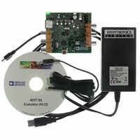
EVAL-ADV7180LFEBZ
Description
BOARD EVAL FOR ADV7180 LFCSP
Manufacturer
Analog Devices Inc
Specifications of EVAL-ADV7180LFEBZ
Main Purpose
Video, SDTV Video Decoder - NTSC, PAL, SECAM
Embedded
No
Utilized Ic / Part
ADV7180
Primary Attributes
CVBS (Composite), Y/C (S-video), and YPrPb (Component) Inputs
Secondary Attributes
8-bit ITU-R BT.656 YCrCb 4:2:2 Output
Lead Free Status / RoHS Status
Lead free / RoHS Compliant
Available stocks
Company
Part Number
Manufacturer
Quantity
Price
Company:

Part Number:
EVAL-ADV7180LFEBZ
Manufacturer:
Analog Devices Inc
Quantity:
135


SYNCHRONIZATION OUTPUT SIGNALS
HS Configuration
The following controls allow the user to configure the behavior
of the HS output pin only:
•
•
•
The HS begin (HSB) and HS end (HSE) registers allow the user
to freely position the HS output (pin) within the video line. The
values in HSB[10:0] and HSE[10:0] are measured in pixel units
from the falling edge of HS. Using both values, the user can
program both the position and length of the HS output signal.
HSB[10:0], HS Begin, Address 0x34[6:4], Address 0x35[7:0]
The position of this edge is controlled by placing a binary
number into HSB[10:0]. The number applied offsets the edge
with respect to an internal counter that is reset to 0 immediately
after EAV Code FF, 00, 00, XY (see Figure 35). HSB is set to
00000000010b, which is two LLC clock cycles from count [0].
The default value of HSB[10:0] is 0x02, indicating that the HS
pulse starts two pixels after the falling edge of HS.
Table 64. HS Timing Parameters (See Figure 35)
Standard
NTSC
PAL
Beginning of HS signal via HSB[10:0]
End of HS signal via HSE[10:0]
Polarity of HS using PHS
PIXEL
BUS
LLC
HS
HS Begin Adjust
HSB[10:0] (Default)
00000000010b
00000000010b
ACTIVE
VIDEO
Cr
D
E
Y
FF
00
4 LLC
EAV
HSE[10:0]
00
XY
HS End Adjust
HSE[10:0] (Default)
00000000000b
00000000000b
80
10
HSB[10:0]
80
10
H BLANK
80
Rev. F | Page 45 of 116
Figure 35. HS Timing
HS to Active Video
LLC Clock Cycles, C
in Figure 35 (Default)
272
284
10
C
Characteristic
HSE[10:0], HS End, Address 0x34[2:0], Address 0x36[7:0]
The position of this edge is controlled by placing a binary
number into HSE[10:0]. The number applied offsets the edge
with respect to an internal counter that is reset to 0 immediately
after EAV Code FF, 00, 00, XY (see Figure 35). HSE is set to
00000000000b, which is 0 LLC clock cycles from count [0].
The default value of HSE[10:0] is 00, indicating that the HS
pulse ends 0 pixels after the falling edge of HS.
For example,
•
•
•
PHS, Polarity HS, Address 0x37[7]
The polarity of the HS pin can be inverted using the PHS bit.
When PHS is 0 (default), HS is active high.
When PHS is 1, HS is active low.
FF
To shift the HS toward active video by 20 LLCs, add
20 LLCs to both HSB and HSE, that is,
HSB[10:0] = [00000010110], HSE[10:0] = [00000010100].
To shift the HS away from active video by 20 LLCs, add
1696 LLCs to both HSB and HSE (for NTSC), that is,
HSB[10:0] = [11010100010], HSE[10:0] = [11010100000].
Therefore, 1696 is derived from the NTSC total number of
pixels, 1716.
To move 20 LLCs away from active video, subtract 20 from
1716 and add the result in binary to both HSB[10:0] and
HSE[10:0].
E
00
SAV
00
Active Video Samples/
Line, D in Figure 35
720Y + 720C = 1440
720Y + 720C = 1440
XY
Cb
Y
Cr
ACTIVE VIDEO
Y
D
Cb
Y
Total LLC Clock
Cycles, E in Figure 35
1716
1728
Cr
ADV7180
Related parts for EVAL-ADV7180LFEBZ
Image
Part Number
Description
Manufacturer
Datasheet
Request
R

Part Number:
Description:
IC, ADJ LDO REG, 1.5V TO 5V 250mA MSOP-8
Manufacturer:
Vishay
Datasheet:

Part Number:
Description:
IC, ADJ LDO REG, 1.5V TO 5V 0.6A 8-TSSOP
Manufacturer:
Vishay
Datasheet:
Part Number:
Description:
IC, ADJ LDO REG, 1.5V TO 5V 250mA MSOP-8
Manufacturer:
Vishay
Datasheet:

Part Number:
Description:
IC ADJ LDO REG 1.5V TO 5V 150mA 5-SOT-23
Manufacturer:
Vishay
Datasheet:

Part Number:
Description:
BOARD EVAL AS1324-AD
Manufacturer:
austriamicrosystems
Datasheet:
Part Number:
Description:
IC, ADJ LDO REG, 1.5V TO 5V 0.6A 8-TSSOP
Manufacturer:
Vishay
Datasheet:

Part Number:
Description:
IC, ADJ LDO REG, 1.5V TO 5V, 0.3A, MSOP8
Manufacturer:
Vishay
Datasheet:
Part Number:
Description:
IC, ADJ LDO REG, 1.5V TO 5V, 0.3A, MSOP8
Manufacturer:
Vishay
Datasheet:
Part Number:
Description:
IC, ADJ LDO REG 1.215V TO 5V 0.3A MSOP-8
Manufacturer:
Vishay
Datasheet:
Part Number:
Description:
IC, ADJ LDO REG 1.215V TO 5V 0.3A MSOP-8
Manufacturer:
Vishay
Datasheet:

Part Number:
Description:
±1.7g Dual-Axis IMEMS Accelerometer Evaluation Board
Manufacturer:
Analog Devices Inc
Datasheet:

Part Number:
Description:
IC MULTIPLIER ANALOG 8-SOIC T/R
Manufacturer:
Analog Devices Inc
Datasheet:

Part Number:
Description:
IC ANALOG MULTIPLIER 8-DIP
Manufacturer:
Analog Devices Inc
Datasheet:
Part Number:
Description:
IC ANALOG MULTIPLIER 8-SOIC
Manufacturer:
Analog Devices Inc
Datasheet:
Part Number:
Description:
IC ANALOG MULTIPLIER 8-DIP
Manufacturer:
Analog Devices Inc
Datasheet: