EVAL-ADV7180LFEBZ Analog Devices Inc, EVAL-ADV7180LFEBZ Datasheet - Page 65
EVAL-ADV7180LFEBZ
Manufacturer Part Number
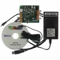
EVAL-ADV7180LFEBZ
Description
BOARD EVAL FOR ADV7180 LFCSP
Manufacturer
Analog Devices Inc
Specifications of EVAL-ADV7180LFEBZ
Main Purpose
Video, SDTV Video Decoder - NTSC, PAL, SECAM
Embedded
No
Utilized Ic / Part
ADV7180
Primary Attributes
CVBS (Composite), Y/C (S-video), and YPrPb (Component) Inputs
Secondary Attributes
8-bit ITU-R BT.656 YCrCb 4:2:2 Output
Lead Free Status / RoHS Status
Lead free / RoHS Compliant
Available stocks
Company
Part Number
Manufacturer
Quantity
Price
Company:

Part Number:
EVAL-ADV7180LFEBZ
Manufacturer:
Analog Devices Inc
Quantity:
135


VPS/PDC/UTC/GEMSTAR
The readback registers for VPS, PDC, and UTC are shared.
Gemstar is a high data rate standard and is available only through
the ancillary stream. However, for evaluation purposes, any one
line of Gemstar is available through the I
same register space as PDC, UTC, and VPS. Therefore, only VPS,
PDC, UTC, or Gemstar can be read through the I
To identify the data that should be made available in the I
registers, the user must program I
(Register Address 0x9C, user sub map).
I
User Sub Map
Specifies which standard result is available for I
GS_PDC_VPS_UTC_CLEAR, GS/PDC/VPS/UTC Clear,
Address 0x78[4], User Sub Map, Write Only, Self-Clearing
Setting GS_PDC_VPS_UTC_CLEAR to 1 reinitializes the
GS/PDC/VPS/UTC data readback registers.
GS_PDC_VPS_UTC_AVL, GS/PDC/VPS/UTC Available,
Address 0x78[4], User Sub Map, Read Only
When GS_PDC_VPS_UTC_AVL is 0, no GS, PDC, VPS, or
UTC data was detected.
When GS_PDC_VPS_UTC_AVL is 1, one GS, PDC, VPS, or
UTC data was detected.
VDP_GS_VPS_PDC_UTC, Readback Registers,
Address 0x84 to Address 0x90
See Table 85 for information on the readback registers.
VPS
The VPS data bits are biphase decoded by the VDP. The decoded
data is available in both the ancillary stream and in the I
readback registers. VPS decoded data is available in the
VDP_GS_VPS_PDC_UTC_0 to VDP_VPS_PDC_UTC_12
registers (Address 0x84 to Address 0x90, User Sub Map). The
GS_PDC_VPS_UTC_AVL bit is set if the user programmed
I
Gemstar
The Gemstar-decoded data is made available in the ancillary
stream, and any one line of Gemstar is also available in the I
registers for evaluation purposes. To read Gemstar results
through the I
I
Table 84. I
I
00 (default)
01
10
11
2
2
2
2
C_GS_VPS_PDC_UTC[1:0]
C_GS_VPS_PDC_UTC to 01, as explained in Table 84.
C_GS_VPS_PDC_UTC to 00, as explained in Table 84.
C_GS_VPS_PDC_UTC[1:0] (VDP), Address 0x9C[7:6],
2
C_GS_VPS_PDC_UTC[1:0] Function
2
C registers, the user must program
2
C_GS_VPS_PDC_UTC[1:0]
Description
Gemstar 1×/2×
VPS
PDC
UTC
2
C registers sharing the
2
2
C at one time.
C readback.
2
C
2
C
2
Rev. F | Page 65 of 116
C
VDP supports autodetection of the Gemstar standard,
either Gemstar 1× or Gemstar 2×, and decodes accordingly.
For the autodetection mode to work, the user must set the
AUTO_DETECT_GS_TYPE bit (Register 0x61, user sub map)
and program the decoder to decode Gemstar 2× on the required
lines through line programming. The type of Gemstar decoded
can be determined by observing the GS_DATA_TYPE bit
(Register 0x78, user sub map).
AUTO_DETECT_GS_TYPE, Address 0x61[4], User Sub Map
Setting AUTO_DETECT_GS_TYPE to 0 (default) disables the
autodetection of the Gemstar type.
Setting AUTO_DETECT_GS_TYPE to 1 enables the
autodetection of the Gemstar type.
GS_DATA_TYPE, Address 0x78[5], User Sub Map, Read Only
Identifies the decoded Gemstar data type.
When GS_DATA_TYPE is 0, Gemstar 1× mode is detected.
Read two data bytes from 0x84.
When GS_DATA_TYPE is 1, Gemstar 2× mode is detected.
Read four data bytes from 0x84.
The Gemstar data that is available in the I
from any line of the input video on which Gemstar was decoded.
To read the Gemstar data on a particular video line, the user
should use the manual configuration described in Table 70 and
Table 71 and enable Gemstar decoding only on the required line.
PDC/UTC
PDC and UTC are data transmitted through Teletext Packet 8/30
Format 2 (Magazine 8, Row 30, Design Code 2 or Design Code 3)
and Packet 8/30 Format 1 (Magazine 8, Row 30, Design Code 0
or Design Code 1). Therefore, if PDC or UTC data is to be read
through I
System B) should be decoded by VDP. The whole teletext
decoded packet is output on the ancillary data stream. The user
can look for the magazine number, row number, and design
code and qualify the data as PDC, UTC, or neither of these.
If PDC/UTC packets are identified, Byte 0 to Byte 12 are updated
to the VDP_GS_VPS_PDC_UTC_0 to VDP_VPS_PDC_UTC_12
registers, and the GS_PDC_VPS_UTC_AVL bit is set. The full
packet data is also available in the ancillary data format.
Note that the data available in the I
status of the WST_PKT_DECODE_DISABLE bit (Bit 3,
Subaddress 0x60, user sub map).
2
C, the corresponding teletext standard (WST or PAL
2
C register depends on the
2
C register can be
ADV7180
Related parts for EVAL-ADV7180LFEBZ
Image
Part Number
Description
Manufacturer
Datasheet
Request
R

Part Number:
Description:
IC, ADJ LDO REG, 1.5V TO 5V 250mA MSOP-8
Manufacturer:
Vishay
Datasheet:

Part Number:
Description:
IC, ADJ LDO REG, 1.5V TO 5V 0.6A 8-TSSOP
Manufacturer:
Vishay
Datasheet:
Part Number:
Description:
IC, ADJ LDO REG, 1.5V TO 5V 250mA MSOP-8
Manufacturer:
Vishay
Datasheet:

Part Number:
Description:
IC ADJ LDO REG 1.5V TO 5V 150mA 5-SOT-23
Manufacturer:
Vishay
Datasheet:

Part Number:
Description:
BOARD EVAL AS1324-AD
Manufacturer:
austriamicrosystems
Datasheet:
Part Number:
Description:
IC, ADJ LDO REG, 1.5V TO 5V 0.6A 8-TSSOP
Manufacturer:
Vishay
Datasheet:

Part Number:
Description:
IC, ADJ LDO REG, 1.5V TO 5V, 0.3A, MSOP8
Manufacturer:
Vishay
Datasheet:
Part Number:
Description:
IC, ADJ LDO REG, 1.5V TO 5V, 0.3A, MSOP8
Manufacturer:
Vishay
Datasheet:
Part Number:
Description:
IC, ADJ LDO REG 1.215V TO 5V 0.3A MSOP-8
Manufacturer:
Vishay
Datasheet:
Part Number:
Description:
IC, ADJ LDO REG 1.215V TO 5V 0.3A MSOP-8
Manufacturer:
Vishay
Datasheet:

Part Number:
Description:
±1.7g Dual-Axis IMEMS Accelerometer Evaluation Board
Manufacturer:
Analog Devices Inc
Datasheet:

Part Number:
Description:
IC MULTIPLIER ANALOG 8-SOIC T/R
Manufacturer:
Analog Devices Inc
Datasheet:

Part Number:
Description:
IC ANALOG MULTIPLIER 8-DIP
Manufacturer:
Analog Devices Inc
Datasheet:
Part Number:
Description:
IC ANALOG MULTIPLIER 8-SOIC
Manufacturer:
Analog Devices Inc
Datasheet:
Part Number:
Description:
IC ANALOG MULTIPLIER 8-DIP
Manufacturer:
Analog Devices Inc
Datasheet: