KIT35XS3400EVBE Freescale Semiconductor, KIT35XS3400EVBE Datasheet - Page 23
KIT35XS3400EVBE
Manufacturer Part Number
KIT35XS3400EVBE
Description
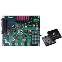
KIT EVALUATION FOR MC35XS3400
Manufacturer
Freescale Semiconductor
Specifications of KIT35XS3400EVBE
Main Purpose
Automotive Lighting
Utilized Ic / Part
*
Primary Attributes
4 protected high-side switches
Secondary Attributes
SPI Interface
Silicon Manufacturer
Freescale
Silicon Core Number
MC35XS3400
Kit Application Type
Power Management
Application Sub Type
EXtreme Switch
Kit Contents
Evaluation Board, CD
Rohs Compliant
Yes
Lead Free Status / RoHS Status
Lead free / RoHS Compliant
Embedded
-
Lead Free Status / Rohs Status
Lead free / RoHS Compliant


Fail-safe and Fault.
contained in succeeding paragraphs.
depending on IN[x] input.
the following signals:
SLEEP MODE
Analog Integrated Circuit Device Data
Freescale Semiconductor
IN_ON[x]
IN[x]
The 35XS3400 has four operating modes: Sleep, Normal,
The
The 35XS3400 transits to operating modes according to
• wake-up =
• fail = (V
• fault = OC[0:3] or OT[0:3] or SC[0:3] or UV
The 35XS3400 is in Sleep mode when:
• V
• wake-up = 0,
• fail = X,
• fault = X.
IN_ON[2] or IN_ON[3],
time-out and FSI input not shorted to ground ),
( UV ) or ( OV and OV_dis ).
PWR
Figure 10
and V
Figure 10. IN_ON[x] internal signal
Fail-Safe
DD
Failure and VDD_FAIL_en) or ( Watchdog
RST
describes an internal signal called IN_ON[x]
DD
Table 6
(wake-up=0)
are within the normal voltage range,
or WAKE or IN_ON[0] or IN_ON[1] or
and
(wake-up=1) and
(fail=1)
and (fault=0)
Figure 11
(fail=1) and
(wake-up=1)
and (fault=1)
summarize details
(fail=0) and (wake-up=1) and (fault=0)
(fail=1) and (wake-up=1) and (fault=0)
(fail=1)
(wake-up=1)
and (fault=0)
t
IN
(wake-up=0)
Figure 11. Operating Modes
OPERATIONAL MODES
and
Fault
Sleep
battery voltage (VPWR) prior to any I/O transitions. This is
also the state of the device when the WAKE and
IN_ON[0:3] are logic [0]. In the Sleep mode, the output and
all unused internal circuitry, such as the internal regulator, are
off to minimize draw current. In addition, all SPI-configurable
features of the device are as if set to logic [0].
Table 6. 35XS3400 Operating Modes
Fail-safe
Normal
x = Don’t care.
(wake-up=1)
and (fault=1)
Mode
Sleep
Fault
This is the Default mode of the device after first applying
wake-up
(fail=0)
(wake-up=1)
and (fault=1)
(fail=0)
(wake-up=1)
and (fault=0)
0
1
1
1
(fail=0) and (wake-up=1) and (fault=0)
(wake-up=0)
fail fault
and
0
1
X
x
and
0
0
1
FUNCTIONAL DEVICE OPERATION
x
Normal
Device is in Sleep mode. All
outputs are OFF.
Device is currently in Normal
mode. Watchdog is active if
enabled.
Device is currently in Fail-safe
mode due to watchdog timeout
or V
output states depend on the
corresponding input in case
FSI is open.
Device is currently in Fault
mode. The faulted output(s) is
(are) OFF. The safe autoretry
circuitry is active to turn-on
again the output(s).
DD
OPERATIONAL MODES
Failure conditions. The
Comments
RST
35XS3400
and
23
Related parts for KIT35XS3400EVBE
Image
Part Number
Description
Manufacturer
Datasheet
Request
R

Part Number:
Description:
Manufacturer:
Freescale Semiconductor, Inc
Datasheet:
Part Number:
Description:
Manufacturer:
Freescale Semiconductor, Inc
Datasheet:
Part Number:
Description:
Manufacturer:
Freescale Semiconductor, Inc
Datasheet:
Part Number:
Description:
Manufacturer:
Freescale Semiconductor, Inc
Datasheet:
Part Number:
Description:
Manufacturer:
Freescale Semiconductor, Inc
Datasheet:
Part Number:
Description:
Manufacturer:
Freescale Semiconductor, Inc
Datasheet:
Part Number:
Description:
Manufacturer:
Freescale Semiconductor, Inc
Datasheet:
Part Number:
Description:
Manufacturer:
Freescale Semiconductor, Inc
Datasheet:
Part Number:
Description:
Manufacturer:
Freescale Semiconductor, Inc
Datasheet:
Part Number:
Description:
Manufacturer:
Freescale Semiconductor, Inc
Datasheet:
Part Number:
Description:
Manufacturer:
Freescale Semiconductor, Inc
Datasheet:
Part Number:
Description:
Manufacturer:
Freescale Semiconductor, Inc
Datasheet:
Part Number:
Description:
Manufacturer:
Freescale Semiconductor, Inc
Datasheet:
Part Number:
Description:
Manufacturer:
Freescale Semiconductor, Inc
Datasheet:
Part Number:
Description:
Manufacturer:
Freescale Semiconductor, Inc
Datasheet: