KIT35XS3400EVBE Freescale Semiconductor, KIT35XS3400EVBE Datasheet - Page 29
KIT35XS3400EVBE
Manufacturer Part Number
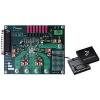
KIT35XS3400EVBE
Description
KIT EVALUATION FOR MC35XS3400
Manufacturer
Freescale Semiconductor
Specifications of KIT35XS3400EVBE
Main Purpose
Automotive Lighting
Utilized Ic / Part
*
Primary Attributes
4 protected high-side switches
Secondary Attributes
SPI Interface
Silicon Manufacturer
Freescale
Silicon Core Number
MC35XS3400
Kit Application Type
Power Management
Application Sub Type
EXtreme Switch
Kit Contents
Evaluation Board, CD
Rohs Compliant
Yes
Lead Free Status / RoHS Status
Lead free / RoHS Compliant
Embedded
-
Lead Free Status / Rohs Status
Lead free / RoHS Compliant


Open-load Detection In On State
chosen by SPI to detect a standard bulbs or LEDs
(OLLED[0:3] bit set to logic [1]). In cases where the load
current drops below the defined current threshold, the OLON
bit will be set to a logic [1], the output will stay ON and FS will
not be disturbed.
Open-load Detection In On State For Led
detected periodically each t
detect OLLED in fully-on state, the output must be ON at least
t
and SPI read operation is needed (OL_ON[0:3] bit). The ON
output open-load protection can be disabled through SPI
(OLON_DIS[0:3] bit).
Analog Current Recopy and Temperature Feedbacks
proportional to the designed output current or a voltage
proportional to the temperature of the GND flag (pin #14).
The routing is SPI programmable (TEMP_en, CSNS_en,
CSNS_s[1,0] and CSNS_ratio_s bits).
delivers current only during ON time of the output switch
without overshoot. The maximum current is 2.0 mA typical.
The typical value of external CSNS resistor connected to the
ground is 4.7 k
Temperature Prewarning Detection
prewarning reported via SPI in case of the temperature of the
GND flag is higher than T
to [1]) is latched in the SPI DIAGR0 register. To delatch, a
read SPI command is needed.
ACTIVE CLAMP ON VPWR
to limit the maximum transient VPWR voltage at
VPWR
corresponding output is turned off which leads to high-
voltage at VPWR with an inductive VPWR line. When VPWR
voltage exceeds VPWR
corresponding output is deactivated and all HS[0:3] outputs
are switched ON automatically to demagnetize the inductive
Battery line.
(> 20 meters), the smart high side switch output may exceed
the energy capability in case of a short-circuit. It is
recommended to implement a voltage transient suppressor
to drain the battery line energy.
Analog Integrated Circuit Device Data
Freescale Semiconductor
OLLED.
The ON output open-load current thresholds can be
Open load for LEDs only (OLLED[0:3] set to logic [1]) is
To delatch the diagnosis, the condition should be removed
The CSNS pin is an analog output reporting a current
In case the current recopy is active, the CSNS output
The current recopy is not active in Fail-safe mode.
In Normal mode, the 35XS3400 provides a temperature
The device provides an active gate clamp circuit in order
For a long battery line between the battery and the device
(CLAMP)
. In case of overload on an output the
Ω
.
(CLAMP)
OTWAR
OLLED
. This diagnosis (OTW bit set
threshold, the turn-off on the
(fully-on, D[6:0]=7F). To
REVERSE BATTERY ON VPWR
low as -18 V. Under these conditions, the ON resistance of
the output is 2 times higher than typical ohmic value in
forward mode. No additional passive components are
required except on V
GROUND DISCONNECT PROTECTION
load ground, the device protects itself and safely turns OFF
the output regardless of the state of the output at the time of
disconnection (maximum VPWR=16 V). A 10 k
needs to be added between the MCU and each digital input
pin in order to ensure that the device turns off in case of
ground disconnect and to prevent this pin from exceeding
maximum ratings.
LOSS OF SUPPLY LINES
Loss of VDD
specification: V
logic [1]), all SPI register content is reset.
if V
uses the battery input to power the output MOSFET-related
current sense circuitry and any other internal logic providing
Fail-safe device operation with no V
the over-temperature, over-current, severe short-circuit,
short to VPWR and OFF open-load circuitry are fully
operational with default values corresponding to all SPI bits
are set to logic [0]. No current is conducted from VPWR to
V
Loss of VPWR
specification), the SPI configuration, reporting, and daisy
chain features are provided for RST is set to logic [1] under
V
diagnosed with a UV fault in the SPI STATS_s registers. The
SPI pull-up and pull-down current sources are not
operational. The previous device configuration is maintained.
No current is conducted from VDD to VPWR.
Loss of VPWR and VDD
(or not within specification: (VDD and VPWR) <
V
values corresponding to all SPI bits are set to logic [0] and all
latched faults are also reset.
DD
DD
SUPPLY(POR)
The output survives the application of reverse voltage as
In the event the 35XS3400 ground is disconnected from
If the external V
The outputs can still be driven by the direct inputs IN[0 : 3]
If the external VPWR supply is disconnected (or not within
If the external VPWR and VDD supplies are disconnected
PWR
.
in nominal conditions. This fault condition can be
is within specified voltage range. The 35XS3400
), all SPI register contents are reset with default
DD
PROTECTION AND DIAGNOSTIC FEATURES
<V
DD
DD(FAIL))
DD
supply is disconnected (or not within
current path.
FUNCTIONAL DEVICE OPERATION
with VDD_FAIL_en bit is set to
DD
supplied. In this state,
Ω
resistor
35XS3400
29
Related parts for KIT35XS3400EVBE
Image
Part Number
Description
Manufacturer
Datasheet
Request
R

Part Number:
Description:
Manufacturer:
Freescale Semiconductor, Inc
Datasheet:
Part Number:
Description:
Manufacturer:
Freescale Semiconductor, Inc
Datasheet:
Part Number:
Description:
Manufacturer:
Freescale Semiconductor, Inc
Datasheet:
Part Number:
Description:
Manufacturer:
Freescale Semiconductor, Inc
Datasheet:
Part Number:
Description:
Manufacturer:
Freescale Semiconductor, Inc
Datasheet:
Part Number:
Description:
Manufacturer:
Freescale Semiconductor, Inc
Datasheet:
Part Number:
Description:
Manufacturer:
Freescale Semiconductor, Inc
Datasheet:
Part Number:
Description:
Manufacturer:
Freescale Semiconductor, Inc
Datasheet:
Part Number:
Description:
Manufacturer:
Freescale Semiconductor, Inc
Datasheet:
Part Number:
Description:
Manufacturer:
Freescale Semiconductor, Inc
Datasheet:
Part Number:
Description:
Manufacturer:
Freescale Semiconductor, Inc
Datasheet:
Part Number:
Description:
Manufacturer:
Freescale Semiconductor, Inc
Datasheet:
Part Number:
Description:
Manufacturer:
Freescale Semiconductor, Inc
Datasheet:
Part Number:
Description:
Manufacturer:
Freescale Semiconductor, Inc
Datasheet:
Part Number:
Description:
Manufacturer:
Freescale Semiconductor, Inc
Datasheet: