KIT35XS3400EVBE Freescale Semiconductor, KIT35XS3400EVBE Datasheet - Page 30
KIT35XS3400EVBE
Manufacturer Part Number
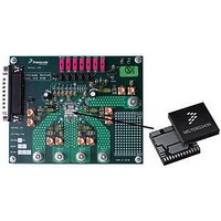
KIT35XS3400EVBE
Description
KIT EVALUATION FOR MC35XS3400
Manufacturer
Freescale Semiconductor
Specifications of KIT35XS3400EVBE
Main Purpose
Automotive Lighting
Utilized Ic / Part
*
Primary Attributes
4 protected high-side switches
Secondary Attributes
SPI Interface
Silicon Manufacturer
Freescale
Silicon Core Number
MC35XS3400
Kit Application Type
Power Management
Application Sub Type
EXtreme Switch
Kit Contents
Evaluation Board, CD
Rohs Compliant
Yes
Lead Free Status / RoHS Status
Lead free / RoHS Compliant
Embedded
-
Lead Free Status / Rohs Status
Lead free / RoHS Compliant


EMC PERFORMANCES
board in accordance with the typical application schematic.
SERIAL INPUT COMMUNICATION
messages. A message is transmitted by the MCU starting
with the MSB D15 and ending with the LSB, D0
Each incoming command message on the SI pin can be
interpreted using the following bit assignments: the MSB,
D15, is the watchdog bit (WDIN). In some cases, output
selection is done with bits D14 : D13. The next three bits,
D12: D10, are used to select the command register. The
30
35XS3400
Table 10. SI Message Bit Assignment
Table 11. Serial Input Address and Configuration Bit Map
V
FUNCTIONAL DEVICE OPERATION
LOGIC COMMANDS AND REGISTERS
V
CONFR0_s WDI
CONFR1_s WDI
state after
Register
condition
RST=0 or
STATR_s
PWMR_s
Register
DD(FAIL)
SUPPLY(PO
OCR_s
All following tests are performed on Freescale evaluation
SPI communication is accomplished using 16-bit
CALR
GCR
SI
R)
Bit Sig
MSB
LSB
or
D15
WDI
WDI
WDI
WDI
WDI
N
N
N
N
N
N
N
0
D1
A
A
A
A
4
X
0
0
0
1
1
1
1
D1
A
A
A
A
3
X
0
0
0
0
0
0
0
SI Msg Bit
D1
D14
D12
2
0
0
0
0
1
1
1
X
D8:D0
D15
D9
D1
:
:
X
1
0
0
1
1
0
0
1
D13
D10
D1
0
X
0
1
0
1
0
1
1
D9
0
0
0
0
0
0
0
0
VDD_F
AIL_en
D8
LOGIC COMMANDS AND REGISTERS
0
0
0
0
0
1
0
Watchdog in: toggled to satisfy watchdog requirements.
Register address bits used in some cases for output selection (
Register address bits.
Not used (set to logic [0]).
Used to configure the inputs, outputs, and the device protection features and SO status content.
PWM_en CLOCK_sel TEMP_en
BC1_s
ON_s
(Table
D7
0
0
0
0
0
unlimited_s
10).
PWM6_s
Retry_
BC0_s
D6
0
0
0
0
Retry_dis_s OS_dis_s OLON_dis_s OLOFF_dis_
SI Data
DIR_dis_s
PWM5_s
transients on the VPWR line (per ISO 7637-2).
CISPR25 emission standard and 200 V/m or BCI 200 mA
injection level for immunity tests.
remaining nine bits, D8 : D0, are used to configure and control
the outputs and their protection features.
accommodate those applications where daisy-chaining is
desirable, or to confirm transmitted data, as long as the
messages are all multiples of 16 bits. Any attempt made to
latch in a message that is not 16 bits will be ignored.
configure the device and to control the state of the outputs.
Table 11
OC1_s
D5
0
0
0
The device is protected in case of positive and negative
The 35XS3400 successfully meets the Class 5 of the
Multiple messages can be transmitted in succession to
The 35XS3400 has defined registers, which are used to
Message Bit Description
CSNS_en
PWM4_s
summarizes the SI registers.
SR1_s
OC0_s
SOA4
D4
1
0
PWM3_s
OCHI_s
CSNS1
SR0_s
SOA3
D3
Analog Integrated Circuit Device Data
1
0
DELAY2_s
OCLO1_s
PWM2_s
Table 12
CSNS0
SOA2
D2
s
0
0
Freescale Semiconductor
).
OCLCO0_s OC_mode_
OLLED_en
DELAY1_s DELAY0_s
PWM1_s
SOA1
D1
_s
X
1
0
CSNS_ratio
PWM0_s
OV_dis
SOA0
D0
_s
s
1
0
Related parts for KIT35XS3400EVBE
Image
Part Number
Description
Manufacturer
Datasheet
Request
R

Part Number:
Description:
Manufacturer:
Freescale Semiconductor, Inc
Datasheet:
Part Number:
Description:
Manufacturer:
Freescale Semiconductor, Inc
Datasheet:
Part Number:
Description:
Manufacturer:
Freescale Semiconductor, Inc
Datasheet:
Part Number:
Description:
Manufacturer:
Freescale Semiconductor, Inc
Datasheet:
Part Number:
Description:
Manufacturer:
Freescale Semiconductor, Inc
Datasheet:
Part Number:
Description:
Manufacturer:
Freescale Semiconductor, Inc
Datasheet:
Part Number:
Description:
Manufacturer:
Freescale Semiconductor, Inc
Datasheet:
Part Number:
Description:
Manufacturer:
Freescale Semiconductor, Inc
Datasheet:
Part Number:
Description:
Manufacturer:
Freescale Semiconductor, Inc
Datasheet:
Part Number:
Description:
Manufacturer:
Freescale Semiconductor, Inc
Datasheet:
Part Number:
Description:
Manufacturer:
Freescale Semiconductor, Inc
Datasheet:
Part Number:
Description:
Manufacturer:
Freescale Semiconductor, Inc
Datasheet:
Part Number:
Description:
Manufacturer:
Freescale Semiconductor, Inc
Datasheet:
Part Number:
Description:
Manufacturer:
Freescale Semiconductor, Inc
Datasheet:
Part Number:
Description:
Manufacturer:
Freescale Semiconductor, Inc
Datasheet: