AT91SAM9G10-EK Atmel, AT91SAM9G10-EK Datasheet - Page 179
AT91SAM9G10-EK
Manufacturer Part Number
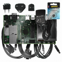
AT91SAM9G10-EK
Description
KIT DEV FOR SAM9G10 ARM
Manufacturer
Atmel
Type
MCUr
Specifications of AT91SAM9G10-EK
Contents
Board, Cables, Power Supply
Silicon Manufacturer
Atmel
Core Architecture
AVR
Kit Contents
Board
Svhc
No SVHC (15-Dec-2010)
Mcu Supported Families
AT91SAM9G10, ARM926EJ-S
Tool / Board Applications
Microcontroller
Rohs Compliant
Yes
For Use With/related Products
*
Lead Free Status / RoHS Status
Contains lead / RoHS non-compliant


22.10 Data Float Wait States
22.10.1
6462A–ATARM–03-Jun-09
READ_MODE
Some memory devices are slow to release the external bus. For such devices, it is necessary to
add wait states (data float wait states) after a read access:
The Data Float Output Time (t
TDF_CYCLES field of the SMC_MODE register for the corresponding chip select. The value of
TDF_CYCLES indicates the number of data float wait cycles (between 0 and 15) before the
external device releases the bus, and represents the time allowed for the data output to go to
high impedance after the memory is disabled.
Data float wait states do not delay internal memory accesses. Hence, a single access to an
external memory with long t
memory.
The data float wait states management depends on the READ_MODE and the TDF_MODE
fields of the SMC_MODE register for the corresponding chip select.
Setting the READ_MODE to 1 indicates to the SMC that the NRD signal is responsible for turn-
ing off the tri-state buffers of the external memory device. The Data Float Period then begins
after the rising edge of the NRD signal and lasts TDF_CYCLES MCK cycles.
When the read operation is controlled by the NCS signal (READ_MODE = 0), the TDF field gives
the number of MCK cycles during which the data bus remains busy after the rising edge of NCS.
Figure 22-20
assuming a data float period of 2 cycles (TDF_CYCLES = 2).
ation when controlled by NCS (READ_MODE = 0) and the TDF_CYCLES parameter equals 3.
• before starting a read access to a different external memory
• before starting a write access to the same device or to a different external one.
illustrates the Data Float Period in NRD-controlled mode (READ_MODE =1),
DF
will not slow down the execution of a program from internal
DF
) for each external memory device is programmed in the
Figure 22-21
AT91SAM9G10
shows the read oper-
179
Related parts for AT91SAM9G10-EK
Image
Part Number
Description
Manufacturer
Datasheet
Request
R

Part Number:
Description:
MCU, MPU & DSP Development Tools KICKSTART KIT FOR AT91SAM9 PLUS
Manufacturer:
IAR Systems

Part Number:
Description:
DEV KIT FOR AVR/AVR32
Manufacturer:
Atmel
Datasheet:

Part Number:
Description:
INTERVAL AND WIPE/WASH WIPER CONTROL IC WITH DELAY
Manufacturer:
ATMEL Corporation
Datasheet:
Part Number:
Description:
Low-Voltage Voice-Switched IC for Hands-Free Operation
Manufacturer:
ATMEL Corporation
Datasheet:
Part Number:
Description:
MONOLITHIC INTEGRATED FEATUREPHONE CIRCUIT
Manufacturer:
ATMEL Corporation
Datasheet:
Part Number:
Description:
AM-FM Receiver IC U4255BM-M
Manufacturer:
ATMEL Corporation
Datasheet:
Part Number:
Description:
Monolithic Integrated Feature Phone Circuit
Manufacturer:
ATMEL Corporation
Datasheet:
Part Number:
Description:
Multistandard Video-IF and Quasi Parallel Sound Processing
Manufacturer:
ATMEL Corporation
Datasheet:
Part Number:
Description:
High-performance EE PLD
Manufacturer:
ATMEL Corporation
Datasheet:
Part Number:
Description:
8-bit Flash Microcontroller
Manufacturer:
ATMEL Corporation
Datasheet:
Part Number:
Description:
2-Wire Serial EEPROM
Manufacturer:
ATMEL Corporation
Datasheet: