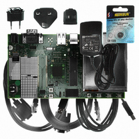
AT91SAM9G10-EK Atmel, AT91SAM9G10-EK Datasheet - Page 552

AT91SAM9G10-EK
Manufacturer Part Number
AT91SAM9G10-EK
Description
KIT DEV FOR SAM9G10 ARM
Manufacturer
Atmel
Type
MCUr
Specifications of AT91SAM9G10-EK
Contents
Board, Cables, Power Supply
Silicon Manufacturer
Atmel
Core Architecture
AVR
Kit Contents
Board
Svhc
No SVHC (15-Dec-2010)
Mcu Supported Families
AT91SAM9G10, ARM926EJ-S
Tool / Board Applications
Microcontroller
Rohs Compliant
Yes
For Use With/related Products
*
Lead Free Status / RoHS Status
Contains lead / RoHS non-compliant
- Current page: 552 of 730
- Download datasheet (12Mb)
35.5
35.5.1
35.5.2
35.5.3
35.6
Figure 35-3. Multimedia Memory Card Bus Topology
6462A–ATARM–03-Jun-09
Product Dependencies
Bus Topology
I/O Lines
Power Management
Interrupt
The pins used for interfacing the MultiMedia Cards or SD Cards may be multiplexed with PIO
lines. The programmer must first program the PIO controllers to assign the peripheral functions
to MCI pins.
Table 35-2.
The MCI may be clocked through the Power Management Controller (PMC), so the programmer
must first configure the PMC to enable the MCI clock.
The MCI interface has an interrupt line connected to the Advanced Interrupt Controller (AIC).
Handling the MCI interrupt requires programming the AIC before configuring the MCI.
Table 35-3.
The MultiMedia Card communication is based on a 7-pin serial bus interface. It has three com-
munication lines and four supply lines.
Table 35-4.
Pin
Number
1
2
3
4
Instance
Instance
MCI
MCI
MCI
MCI
MCI
MCI
MCI
I/O Lines
Peripheral IDs
Bus Topology
Name
RSV
CMD
VSS1
VDD
ID
9
1
9 1011
2 3 4 5 6
Type
NC
I/O/PP/OD
S
S
1213 8
(1)
MCCDA
MCDA0
MCDA1
MCDA2
MCDA3
Signal
MCCK
7
Description
Not connected
Command/response
Supply voltage ground
Supply voltage
I/O Line
AT91SAM9G10
PA1
PA2
PA0
PA4
PA5
PA6
MCCDz
MCI Pin Name
(Slot z)
-
VSS
VDD
Peripheral
(2)
B
B
B
B
B
B
552
Related parts for AT91SAM9G10-EK
Image
Part Number
Description
Manufacturer
Datasheet
Request
R

Part Number:
Description:
MCU, MPU & DSP Development Tools KICKSTART KIT FOR AT91SAM9 PLUS
Manufacturer:
IAR Systems

Part Number:
Description:
DEV KIT FOR AVR/AVR32
Manufacturer:
Atmel
Datasheet:

Part Number:
Description:
INTERVAL AND WIPE/WASH WIPER CONTROL IC WITH DELAY
Manufacturer:
ATMEL Corporation
Datasheet:

Part Number:
Description:
Low-Voltage Voice-Switched IC for Hands-Free Operation
Manufacturer:
ATMEL Corporation
Datasheet:

Part Number:
Description:
MONOLITHIC INTEGRATED FEATUREPHONE CIRCUIT
Manufacturer:
ATMEL Corporation
Datasheet:

Part Number:
Description:
AM-FM Receiver IC U4255BM-M
Manufacturer:
ATMEL Corporation
Datasheet:

Part Number:
Description:
Monolithic Integrated Feature Phone Circuit
Manufacturer:
ATMEL Corporation
Datasheet:

Part Number:
Description:
Multistandard Video-IF and Quasi Parallel Sound Processing
Manufacturer:
ATMEL Corporation
Datasheet:

Part Number:
Description:
High-performance EE PLD
Manufacturer:
ATMEL Corporation
Datasheet:

Part Number:
Description:
8-bit Flash Microcontroller
Manufacturer:
ATMEL Corporation
Datasheet:

Part Number:
Description:
2-Wire Serial EEPROM
Manufacturer:
ATMEL Corporation
Datasheet:


