AT91SAM9G10-EK Atmel, AT91SAM9G10-EK Datasheet - Page 76
AT91SAM9G10-EK
Manufacturer Part Number
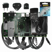
AT91SAM9G10-EK
Description
KIT DEV FOR SAM9G10 ARM
Manufacturer
Atmel
Type
MCUr
Specifications of AT91SAM9G10-EK
Contents
Board, Cables, Power Supply
Silicon Manufacturer
Atmel
Core Architecture
AVR
Kit Contents
Board
Svhc
No SVHC (15-Dec-2010)
Mcu Supported Families
AT91SAM9G10, ARM926EJ-S
Tool / Board Applications
Microcontroller
Rohs Compliant
Yes
For Use With/related Products
*
Lead Free Status / RoHS Status
Contains lead / RoHS non-compliant


13.4
13.4.1
13.4.2
76
Valid Image Detection
AT91SAM9G10
Valid ARM Exception Vectors
Structure of ARM Vector 6
Figure 13-2. Remap Action after Download Completion
The DataFlash Boot software looks for a valid application by analyzing the first 28 bytes corre-
sponding to the ARM exception vectors. These bytes must implement ARM instructions for
either branch or load PC with PC relative addressing.
The sixth vector, at offset 0x14, contains the size of the image to download. The user must
replace this vector with his own vector (see
Figure 13-3. LDR Opcode
Figure 13-4. B Opcode
Unconditional instruction: 0xE for bits 31 to 28
Load PC with PC relative addressing instruction:
The ARM exception vector 6 is used to store information needed by the DataFlash boot pro-
gram. This information is described below.
31
31
1
1
1
1
– Rn = Rd = PC = 0xF
– I==0
– P==1
– U offset added (U==1) or subtracted (U==0)
– W==1
1
1
28 27
28 27
0
0
0x0000_0000
0x0030_0000
0
1
1
0
1
I
24 23
24 23
P
0
U
Internal
Internal
SRAM
ROM
0
W 1
20 19
“Structure of ARM Vector 6” on page
Rn
REMAP
16 15
Offset (24 bits)
Rd
Internal
Internal
SRAM
ROM
12 11
0x0000_0000
0x0010_0000
6462A–ATARM–03-Jun-09
76).
0
0
Related parts for AT91SAM9G10-EK
Image
Part Number
Description
Manufacturer
Datasheet
Request
R

Part Number:
Description:
MCU, MPU & DSP Development Tools KICKSTART KIT FOR AT91SAM9 PLUS
Manufacturer:
IAR Systems

Part Number:
Description:
DEV KIT FOR AVR/AVR32
Manufacturer:
Atmel
Datasheet:

Part Number:
Description:
INTERVAL AND WIPE/WASH WIPER CONTROL IC WITH DELAY
Manufacturer:
ATMEL Corporation
Datasheet:
Part Number:
Description:
Low-Voltage Voice-Switched IC for Hands-Free Operation
Manufacturer:
ATMEL Corporation
Datasheet:
Part Number:
Description:
MONOLITHIC INTEGRATED FEATUREPHONE CIRCUIT
Manufacturer:
ATMEL Corporation
Datasheet:
Part Number:
Description:
AM-FM Receiver IC U4255BM-M
Manufacturer:
ATMEL Corporation
Datasheet:
Part Number:
Description:
Monolithic Integrated Feature Phone Circuit
Manufacturer:
ATMEL Corporation
Datasheet:
Part Number:
Description:
Multistandard Video-IF and Quasi Parallel Sound Processing
Manufacturer:
ATMEL Corporation
Datasheet:
Part Number:
Description:
High-performance EE PLD
Manufacturer:
ATMEL Corporation
Datasheet:
Part Number:
Description:
8-bit Flash Microcontroller
Manufacturer:
ATMEL Corporation
Datasheet:
Part Number:
Description:
2-Wire Serial EEPROM
Manufacturer:
ATMEL Corporation
Datasheet: