AT91SAM9G10-EK Atmel, AT91SAM9G10-EK Datasheet - Page 301
AT91SAM9G10-EK
Manufacturer Part Number
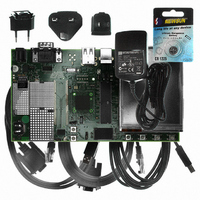
AT91SAM9G10-EK
Description
KIT DEV FOR SAM9G10 ARM
Manufacturer
Atmel
Type
MCUr
Specifications of AT91SAM9G10-EK
Contents
Board, Cables, Power Supply
Silicon Manufacturer
Atmel
Core Architecture
AVR
Kit Contents
Board
Svhc
No SVHC (15-Dec-2010)
Mcu Supported Families
AT91SAM9G10, ARM926EJ-S
Tool / Board Applications
Microcontroller
Rohs Compliant
Yes
For Use With/related Products
*
Lead Free Status / RoHS Status
Contains lead / RoHS non-compliant


Figure 28-10. Character Transmission
28.4.3.3
Figure 28-11. Transmitter Control
28.4.4
6462A–ATARM–03-Jun-09
Shift Register
DBGU_THR
TXEMPTY
TXRDY
DTXD
Peripheral Data Controller
in DBGU_THR
Write Data 0
Transmitter Control
Baud Rate
Example: Parity enabled
DTXD
Clock
S
Data 0
in DBGU_THR
PARE in the mode register DBGU_MR defines whether or not a parity bit is shifted out. When a
parity bit is enabled, it can be selected between an odd parity, an even parity, or a fixed space or
mark bit.
When the transmitter is enabled, the bit TXRDY (Transmitter Ready) is set in the status register
DBGU_SR. The transmission starts when the programmer writes in the Transmit Holding Regis-
ter DBGU_THR, and after the written character is transferred from DBGU_THR to the Shift
Register. The bit TXRDY remains high until a second character is written in DBGU_THR. As
soon as the first character is completed, the last character written in DBGU_THR is transferred
into the shift register and TXRDY rises again, showing that the holding register is empty.
When both the Shift Register and the DBGU_THR are empty, i.e., all the characters written in
DBGU_THR have been processed, the bit TXEMPTY rises after the last stop bit has been
completed.
Both the receiver and the transmitter of the Debug Unit's UART are generally connected to a
Peripheral Data Controller (PDC) channel.
The peripheral data controller channels are programmed via registers that are mapped within
the Debug Unit user interface from the offset 0x100. The status bits are reported in the Debug
Unit status register DBGU_SR and can generate an interrupt.
Write Data 1
Start
Bit
Data 0
D0
Data 0
D1
P
D2
stop
D3
S
D4
D5
Data 1
D6
Data 1
D7
Parity
Bit
AT91SAM9G10
P
Stop
Bit
Data 1
stop
301
Related parts for AT91SAM9G10-EK
Image
Part Number
Description
Manufacturer
Datasheet
Request
R

Part Number:
Description:
MCU, MPU & DSP Development Tools KICKSTART KIT FOR AT91SAM9 PLUS
Manufacturer:
IAR Systems

Part Number:
Description:
DEV KIT FOR AVR/AVR32
Manufacturer:
Atmel
Datasheet:

Part Number:
Description:
INTERVAL AND WIPE/WASH WIPER CONTROL IC WITH DELAY
Manufacturer:
ATMEL Corporation
Datasheet:
Part Number:
Description:
Low-Voltage Voice-Switched IC for Hands-Free Operation
Manufacturer:
ATMEL Corporation
Datasheet:
Part Number:
Description:
MONOLITHIC INTEGRATED FEATUREPHONE CIRCUIT
Manufacturer:
ATMEL Corporation
Datasheet:
Part Number:
Description:
AM-FM Receiver IC U4255BM-M
Manufacturer:
ATMEL Corporation
Datasheet:
Part Number:
Description:
Monolithic Integrated Feature Phone Circuit
Manufacturer:
ATMEL Corporation
Datasheet:
Part Number:
Description:
Multistandard Video-IF and Quasi Parallel Sound Processing
Manufacturer:
ATMEL Corporation
Datasheet:
Part Number:
Description:
High-performance EE PLD
Manufacturer:
ATMEL Corporation
Datasheet:
Part Number:
Description:
8-bit Flash Microcontroller
Manufacturer:
ATMEL Corporation
Datasheet:
Part Number:
Description:
2-Wire Serial EEPROM
Manufacturer:
ATMEL Corporation
Datasheet: