AT91SAM9G10-EK Atmel, AT91SAM9G10-EK Datasheet - Page 690
AT91SAM9G10-EK
Manufacturer Part Number
AT91SAM9G10-EK
Description
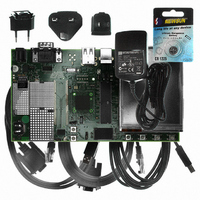
KIT DEV FOR SAM9G10 ARM
Manufacturer
Atmel
Type
MCUr
Specifications of AT91SAM9G10-EK
Contents
Board, Cables, Power Supply
Silicon Manufacturer
Atmel
Core Architecture
AVR
Kit Contents
Board
Svhc
No SVHC (15-Dec-2010)
Mcu Supported Families
AT91SAM9G10, ARM926EJ-S
Tool / Board Applications
Microcontroller
Rohs Compliant
Yes
For Use With/related Products
*
Lead Free Status / RoHS Status
Contains lead / RoHS non-compliant


39.5.3
Table 39-10. Main Oscillator Characteristics
Notes:
690
Symbol
1/(t
C
C
C
t
I
P
I
ST
DDST
DD ON
ON
CRYSTAL
LEXT
INT
CPMAIN
(8)
1. C
2. R
3. R
4. R
5. R
6. Additional user load capacitance should be subtracted from C
7. The C
8. C
(7)
)
AT91SAM9G10
Main Oscillator Characteristics
pF. All parasitic capacitance, package and board, must be calculated in order to reach 12.5 pF (minimum targeted load for
the oscillator) by taking into account the internal load C
capacitance must be: 12.5 pF - 4.4 pF = 8.1 pF which means that 16.2 pF is the target value (16.2 pF from xin to gnd and
16.2 pF from xout to gnd) If 17.5 pF load is targeted, the sum of pad, package, board and external capacitances must be
17.5 pF - 4.4 pF = 13.1 pF which means 26.2 pF (26.2 pF from xin to gnd and 26.2 pF from xout to gnd).
S
S
S
S
S
INT
is the shunt capacitance.
= 100 to 200 Ω ; C
= 50 to 100 Ω ; C
= 25 to 50 Ω ; C
= 20 to 50 Ω ; C
Parameter
Crystal Oscillator Frequency
Crystal Load Capacitance
External Load Capacitance
Internal Load Capacitance
Duty Cycle
Startup Time
Standby Current Consumption
Drive Level
Current Dissipation
includes internal parasitic, package load and internal routing capacitance.
CRYSTAL
value must be specified by the crystal manufacturer. In our case, C
S
S
S
= 2.5 to 3.0 pF; C
= 3.2 to 4.0 pF; C
S
= 2.0 to 2.5 pF; C
= 2.0 to 2.5 pF; C
M
M
Conditions
C
C
V
C
C
C
C
Standby mode
@ 3 MHz
@ 8 MHz
@ 16 MHz
@ 20 MHz
@ 3 MHz
@ 8 MHz
@ 16 MHz
@ 20 MHz
M
C
= 7 to 5 fF (typ, worst case).
= 10 to 8 fF (typ, worst case).
DDPLL
M
CRYSTAL
CRYSTAL
S
S
S
S
XIN
LEXT
= 4 to 3 fF (typ, worst case).
= 3 pF
= 7 pF
= 7 pF
= 7 pF
= 2 to 1.5 fF (typ, worst case) using 1 kΩ serial resistor on XOUT.
= 3 to 3.6V
AT91SAM9G10
= 12.5 pF
= 17.5 pF
(2)
(3)
(1)
(1)
(1)
(1)
(4)
(5)
C
1/(t
1/(t
1/(t
1/(t
CRYSTAL
CPMAIN
CPMAIN
CPMAIN
CPMAIN
INT
. So, to target the minimum oscillator load of 12.5 pF, external
(6) (7)
(6) (7)
) = 3 MHz
) = 8 MHz
) = 16 MHz
) = 20 MHz
LEXT
.
C
XOUT
LEXT
CRYSTAL
12.5
Min
40
3
must be between 12.5 pf and 17.5
16.2
26.2
Typ
230
380
400
550
4.4
16
50
6462A–ATARM–03-Jun-09
Max
17.5
330
530
630
750
20
60
20
15
30
50
50
4
2
2
1
MHz
Unit
µW
ms
pF
pF
pF
pF
µA
µA
%
Related parts for AT91SAM9G10-EK
Image
Part Number
Description
Manufacturer
Datasheet
Request
R

Part Number:
Description:
MCU, MPU & DSP Development Tools KICKSTART KIT FOR AT91SAM9 PLUS
Manufacturer:
IAR Systems

Part Number:
Description:
DEV KIT FOR AVR/AVR32
Manufacturer:
Atmel
Datasheet:

Part Number:
Description:
INTERVAL AND WIPE/WASH WIPER CONTROL IC WITH DELAY
Manufacturer:
ATMEL Corporation
Datasheet:
Part Number:
Description:
Low-Voltage Voice-Switched IC for Hands-Free Operation
Manufacturer:
ATMEL Corporation
Datasheet:
Part Number:
Description:
MONOLITHIC INTEGRATED FEATUREPHONE CIRCUIT
Manufacturer:
ATMEL Corporation
Datasheet:
Part Number:
Description:
AM-FM Receiver IC U4255BM-M
Manufacturer:
ATMEL Corporation
Datasheet:
Part Number:
Description:
Monolithic Integrated Feature Phone Circuit
Manufacturer:
ATMEL Corporation
Datasheet:
Part Number:
Description:
Multistandard Video-IF and Quasi Parallel Sound Processing
Manufacturer:
ATMEL Corporation
Datasheet:
Part Number:
Description:
High-performance EE PLD
Manufacturer:
ATMEL Corporation
Datasheet:
Part Number:
Description:
8-bit Flash Microcontroller
Manufacturer:
ATMEL Corporation
Datasheet:
Part Number:
Description:
2-Wire Serial EEPROM
Manufacturer:
ATMEL Corporation
Datasheet: