AT91SAM9G10-EK Atmel, AT91SAM9G10-EK Datasheet - Page 356
AT91SAM9G10-EK
Manufacturer Part Number
AT91SAM9G10-EK
Description
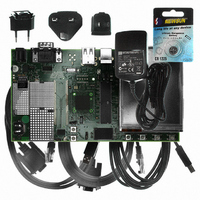
KIT DEV FOR SAM9G10 ARM
Manufacturer
Atmel
Type
MCUr
Specifications of AT91SAM9G10-EK
Contents
Board, Cables, Power Supply
Silicon Manufacturer
Atmel
Core Architecture
AVR
Kit Contents
Board
Svhc
No SVHC (15-Dec-2010)
Mcu Supported Families
AT91SAM9G10, ARM926EJ-S
Tool / Board Applications
Microcontroller
Rohs Compliant
Yes
For Use With/related Products
*
Lead Free Status / RoHS Status
Contains lead / RoHS non-compliant


Figure 30-9. Programmable Delays
30.6.3.5
30.6.3.6
356
Chip Select 1
Chip Select 2
AT91SAM9G10
Peripheral Selection
SPI Peripheral DMA Controller (PDC)
SPCK
These delays allow the SPI to be adapted to the interfaced peripherals and their speed and bus
release time.
The serial peripherals are selected through the assertion of the NPCS0 to NPCS3 signals. By
default, all the NPCS signals are high before and after each transfer.
Fixed Peripheral Select is activated by writing the PS bit to zero in SPI_MR (Mode Register). In
this case, the current peripheral is defined by the PCS field in SPI_MR and the PCS field in the
SPI_TDR has no effect.
Variable Peripheral Select is activated by setting PS bit to one. The PCS field in SPI_TDR is
used to select the current peripheral. This means that the peripheral selection can be defined for
each new data. The value to write in the SPI_TDR register as the following format.
[xxxxxxx(7-bit) + LASTXFER(1-bit)
equals to the chip select to assert as defined in
LASTXFER bit at 0 or 1 depending on CSAAT bit. CSAAT, LASTXFER and CSNAAT bit are dis-
cussed in the Peripheral Deselection in
Note:
In both fixed and variable mode the Peripheral DMA Controller (PDC) can be used to reduce
processor overhead.
The Fixed Peripheral Selection allows buffer transfers with a single peripheral. Using the PDC is
an optimal means, as the size of the data transfer between the memory and the SPI is either 8
bits or 16 bits. However, changing the peripheral selection requires the Mode Register to be
reprogrammed.
The Variable Peripheral Selection allows buffer transfers with multiple peripherals without repro-
gramming the Mode Register. Data written in SPI_TDR is 32 bits wide and defines the real data
to be transmitted and the peripheral it is destined to. Using the PDC in this mode requires 32-bit
wide buffers, with the data in the LSBs and the PCS and LASTXFER fields in the MSBs, how-
• Fixed Peripheral Select: SPI exchanges data with only one peripheral
• Variable Peripheral Select: Data can be exchanged with more than one peripheral without
having to reprogram the NPCS field in the SPI_MR register.
1. Optional.
DLYBCS
DLYBS
(1)
+ xxxx(4-bit) + PCS (4-bit) + DATA (8 to 16-bit)] with PCS
Section
Section 30.7.4
30.6.3.10.
DLYBCT
(SPI Transmit Data Register) and
6462A–ATARM–03-Jun-09
DLYBCT
Related parts for AT91SAM9G10-EK
Image
Part Number
Description
Manufacturer
Datasheet
Request
R

Part Number:
Description:
MCU, MPU & DSP Development Tools KICKSTART KIT FOR AT91SAM9 PLUS
Manufacturer:
IAR Systems

Part Number:
Description:
DEV KIT FOR AVR/AVR32
Manufacturer:
Atmel
Datasheet:

Part Number:
Description:
INTERVAL AND WIPE/WASH WIPER CONTROL IC WITH DELAY
Manufacturer:
ATMEL Corporation
Datasheet:
Part Number:
Description:
Low-Voltage Voice-Switched IC for Hands-Free Operation
Manufacturer:
ATMEL Corporation
Datasheet:
Part Number:
Description:
MONOLITHIC INTEGRATED FEATUREPHONE CIRCUIT
Manufacturer:
ATMEL Corporation
Datasheet:
Part Number:
Description:
AM-FM Receiver IC U4255BM-M
Manufacturer:
ATMEL Corporation
Datasheet:
Part Number:
Description:
Monolithic Integrated Feature Phone Circuit
Manufacturer:
ATMEL Corporation
Datasheet:
Part Number:
Description:
Multistandard Video-IF and Quasi Parallel Sound Processing
Manufacturer:
ATMEL Corporation
Datasheet:
Part Number:
Description:
High-performance EE PLD
Manufacturer:
ATMEL Corporation
Datasheet:
Part Number:
Description:
8-bit Flash Microcontroller
Manufacturer:
ATMEL Corporation
Datasheet:
Part Number:
Description:
2-Wire Serial EEPROM
Manufacturer:
ATMEL Corporation
Datasheet: