MA300012 Microchip Technology, MA300012 Datasheet - Page 14
MA300012
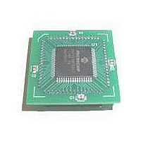
Manufacturer Part Number
MA300012
Description
MODULE DSPIC30F SAMPLE 64QFP
Manufacturer
Microchip Technology
Specifications of MA300012
Module/board Type
dsPIC30F Plug-in Module
Lead Free Status / RoHS Status
Lead free / RoHS Compliant
For Use With/related Products
DM240001
Lead Free Status / RoHS Status
Lead free / RoHS Compliant, Lead free / RoHS Compliant


dsPIC30F
5.3
The core has two data spaces, X and Y. These data
spaces can be considered either separate (for some
DSP instructions), or as one unified linear address
range (for MCU instructions). The data spaces are
accessed using two Address Generation Units (AGUs)
and separate data paths. This feature allows certain
instructions to concurrently fetch two words from RAM,
thereby enabling efficient execution of DSP algorithms
such as Finite Impulse Response (FIR) filtering and
Fast Fourier Transform (FFT).
5.3.1
The X data space is used by all instructions and
supports all addressing modes. There are separate
read and write data buses for X data space. The X read
data bus is the read data path for all instructions that
view data space as combined X and Y address space.
It is also the X data prefetch path for the dual operand
DSP instructions (MAC class).
The Y data space is used in concert with the X data
space by the MAC class of instructions (CLR, ED,
EDAC, MAC, MOVSAC, MPY, MPY.N and MSC) to
provide two concurrent data read paths.
Both the X and Y data spaces support modulo
addressing for all instructions, subject to addressing
mode restrictions. Bit-reversed addressing is only
supported for writes to X data space.
All data memory writes, including in DSP instructions,
view data space as combined X and Y address space.
The boundary between the X and Y data spaces is
device-dependent (an example is shown in Figure 5-3)
and is not user programmable.
All effective addresses are 16 bits wide and point to
bytes within the data space. Therefore, the data space
address range is 64 Kbytes or 32 Kwords, though the
implemented memory locations vary from one device to
another.
DS70043F-page 12
Data Address Space
X AND Y DATA SPACES
5.3.2
The core data width is 16-bits. All internal registers are
organized as 16-bit wide words. Data space memory is
organized in byte addressable, 16-bit wide blocks.
Figure 5-3 depicts a sample data space memory map
for the dsPIC30F.
5.3.3
To
PICmicro
usage efficiency, the dsPIC30F instruction set supports
both word and byte operations. Data is aligned in data
memory and registers as words, but all data space EAs
resolve to bytes. Data byte reads will read the complete
word which contains the byte, using the Least
Significant bit (LSb) of any EA to determine which byte
to select.
As a consequence of this byte accessibility, all effective
address calculations are internally scaled. For
example, the core would recognize that Post-Modified
Register Indirect Addressing mode, [Ws++], will result
in a value of Ws+1 for byte operations and Ws+2 for
word operations.
All word accesses must be aligned to an even address.
Misaligned word data fetches are not supported.
Should a misaligned read or write be attempted, a trap
will then be executed, allowing the system and/or user
to examine the machine state prior to execution of the
address fault.
help
®
devices and improve data space memory
DATA SPACE WIDTH
DATA ALIGNMENT
maintain
backward
© 2005 Microchip Technology Inc.
compatibility
with
Related parts for MA300012
Image
Part Number
Description
Manufacturer
Datasheet
Request
R

Part Number:
Description:
Manufacturer:
Microchip Technology Inc.
Datasheet:
Part Number:
Description:
Manufacturer:
Microchip Technology Inc.
Datasheet:
Part Number:
Description:
Manufacturer:
Microchip Technology Inc.
Datasheet:
Part Number:
Description:
Manufacturer:
Microchip Technology Inc.
Datasheet:
Part Number:
Description:
Manufacturer:
Microchip Technology Inc.
Datasheet:
Part Number:
Description:
Manufacturer:
Microchip Technology Inc.
Datasheet:
Part Number:
Description:
Manufacturer:
Microchip Technology Inc.
Datasheet:
Part Number:
Description:
Manufacturer:
Microchip Technology Inc.
Datasheet: