MA300012 Microchip Technology, MA300012 Datasheet - Page 28
MA300012
Manufacturer Part Number
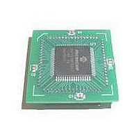
MA300012
Description
MODULE DSPIC30F SAMPLE 64QFP
Manufacturer
Microchip Technology
Specifications of MA300012
Module/board Type
dsPIC30F Plug-in Module
Lead Free Status / RoHS Status
Lead free / RoHS Compliant
For Use With/related Products
DM240001
Lead Free Status / RoHS Status
Lead free / RoHS Compliant, Lead free / RoHS Compliant


dsPIC30F
9.2.2
The Timer2/3 module is a 32-bit timer (which can be
configured as two 16-bit timers) with selectable
operating modes. These timers are used by other
peripheral modules, such as:
• Input Capture
• Output Compare/Simple PWM
Timer2/3 has the following modes:
• Two independent 16-bit timers (Timer2 and
• Single 32-bit timer operation
• Single 32-bit synchronous counter
Further, the following operational characteristics are
supported:
• ADC conversion start trigger
• 32-bit Timer gated by external pulse
• Selectable prescaler settings
• Timer counter operation during Idle and Sleep
• Interrupt on a 32-bit period register match
9.2.3
The Timer4/5 module is similar in operation to the
Timer2/3 module. Differences include:
• The Timer4/5 module does not support the ADC
• Timer 4/5 can not be used by other peripheral
DS70043F-page 26
Timer3) with Timer and Synchronous Counter
modes
modes
event trigger feature
modules, such as Input Capture and Output
Compare
TIMER 2/3
TIMER 4/5
9.3
The Motor Control PWM (MCPWM) module simplifies
the task of generating multiple, synchronized pulse
width modulated outputs. In particular, the following
power and motion control applications are supported:
• Three-Phase AC Induction Motor
• Switched Reluctance (SR) Motor
• Brushless DC (BLDC) Motor
• Uninterrupted Power Supply (UPS)
The PWM module has the following features:
• Dedicated time base supports T
• Two output pins (pair) for each PWM generator
• Complementary or independent operation for
• Hardware dead-time generators for
• Output pin polarity defined by nonvolatile device
• Multiple output modes:
• Manual override register for PWM output pins
• Hardware Fault input pins with programmable
• Trigger for synchronizing A/D samples and
• Each output pin associated with the PWM can be
9.3.1
There are two versions of the MCPWM module
depending on the dsPIC30F device that is selected.
There is an 8-output module that is typically found on
devices that have 64 or more pins. A 6-output MCPWM
module is also available and is typically found on
smaller devices that have fewer than 64 pins.
The 6-output MCPWM module is useful for single or
3-phase power application, while the 8 MCPWM can
support 4-phase motor applications. The 8-output
MCPWM (Figure 9-2) also provides increased flexibility
in an application because it supports two fault pins and
two programmable dead times.
resolution
each output pin pair
Complementary mode
Configuration bits
- Edge-Aligned mode
- Center-Aligned mode
- Center-Aligned mode with double updates
- Single Event mode
function
conversions to PWM timing
individually enabled
Motor Control PWM Module
MCPWM MODULE VARIANTS
© 2005 Microchip Technology Inc.
CY
/2 PWM edge
Related parts for MA300012
Image
Part Number
Description
Manufacturer
Datasheet
Request
R

Part Number:
Description:
Manufacturer:
Microchip Technology Inc.
Datasheet:
Part Number:
Description:
Manufacturer:
Microchip Technology Inc.
Datasheet:
Part Number:
Description:
Manufacturer:
Microchip Technology Inc.
Datasheet:
Part Number:
Description:
Manufacturer:
Microchip Technology Inc.
Datasheet:
Part Number:
Description:
Manufacturer:
Microchip Technology Inc.
Datasheet:
Part Number:
Description:
Manufacturer:
Microchip Technology Inc.
Datasheet:
Part Number:
Description:
Manufacturer:
Microchip Technology Inc.
Datasheet:
Part Number:
Description:
Manufacturer:
Microchip Technology Inc.
Datasheet: