CY3220LINBUS-RD Cypress Semiconductor Corp, CY3220LINBUS-RD Datasheet - Page 17
CY3220LINBUS-RD
Manufacturer Part Number
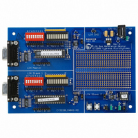
CY3220LINBUS-RD
Description
KIT REF DESIGN LIN BUS
Manufacturer
Cypress Semiconductor Corp
Series
PSoC®r
Datasheet
1.CY3220LINBUS-RD.pdf
(64 pages)
Specifications of CY3220LINBUS-RD
Main Purpose
Interface, LIN
Embedded
Yes, MCU, 8-Bit
Utilized Ic / Part
CY8C27143, CY8C27443
Processor To Be Evaluated
CY8C27143-24PXI and CY8C27443-24PXI
Interface Type
RS-232
Lead Free Status / RoHS Status
Contains lead / RoHS non-compliant
Lead Free Status / RoHS Status
Lead free / RoHS Compliant, Contains lead / RoHS non-compliant
Other names
428-1926


3.1
3.1.1
The software architecture maximizes interrupt processing to
minimize the processing overhead on the end application.
All message processing through configurations is performed
at the interrupt level. Each stage is designed as a state
machine and, upon completion, this state machine unloads
itself and loads in the next required configuration to propa-
gate the message to completion through the LIN message
protocol sequence. Each message scheduled for process-
ing is identified by the identifier byte in the header. The iden-
tifier is defined by the agreed master-slave relationship in
the LIN description file (LDF). See the example LDF in sec-
tion 5,
The master has a Schedule table where the frames are
defined in the sequence in which they are transmitted on the
bus. This table also contains an entry for the duration slot for
each frame. In addition to the Schedule table, there is a Sig-
nal table in which the frames that are used in the system are
defined. This table contains parameters such as the pro-
tected identifier, transfer type, checksum mode, data count,
and the pointer to the frame buffer.
There are three transfer types:
■
■
■
When a MASTER_TO_SLAVE transaction takes place, the
master transmits the content of the frame’s buffer to the
slave. For SLAVE_TO_MASTER, the master receives the
slave’s response and deposits the data in the frame’s buffer.
For a SLAVE_TO_SLAVE transfer, the master discards all
the data received at the end of the frame.
There are two types of checksum modes used, classic and
enhanced. For LIN 1.x slave nodes, use the classic check-
sum for all frames. For LIN 2.0 slave nodes, use enhanced
checksum for frames with identifiers 1 through 59. For iden-
tifiers 60 to 63, use classic checksum. While creating the
Signal table, refer to the LDF to determine the slave version
before deciding the checksum type.
LIN Bus 2.0 Reference Design, Rev. **
3.
MASTER_TO_SLAVE where the master sends the data
after the protected ID for the slave to process.
SLAVE_TO_MASTER where the slave responds with
data to the master’s request.
SLAVE_TO_SLAVE where the master initiates a frame
and the data is transferred from one slave to another.
LIN Description File (LDF) on page
Master Design IP
Software Architecture
Overview
43.
15
The data count also depends upon the slave type. For
LIN1.x slaves, the data count is fixed for different protected
identifiers. For these frames, the data count is set to zero in
the Signal table. When the master comes across a zero for
data count in this table, it assumes that the default data
count is used and extracts the data count from the protected
identifier. For LIN 2.0 slaves, the data count can be from one
to eight. So the data count entry can have any value from
one to eight. Again, this value must be configured after
studying the LDF.
The buffer pointer is an entry that has the address of the
buffer for the particular frame. The master reads from or
writes to the corresponding frame buffer using the buffer
pointer parameter.
3.1.2
The main process must initialize the LIN function and then
set the Schedule table using the l_sch_set function. After
this, the main process performs the actual application. The
successive frame transfers are initiated either inside the
main loop or inside the schedule timer’s interrupt service
routine (ISR). The schedule timer is configured to generate
an interrupt based upon the time base defined in the LDF.
When a frame is read from the Schedule table, the time for
the frame is also read and a loop counter is updated with
this time count. This counter is decremented inside the
schedule timer ISR. When it reaches zero, a flag is set to
indicate that the next frame is ready for processing. The
main
LinMaster_fIsLinReady function. When this flag is set, the
main function calls the l_sch_tick function to start the next
message. Alternatively, the l_sch_tick function can be called
from the schedule timer ISR.
The main program is able to perform other functions inside
the main loop. It checks the status of each frame transfer by
checking the first byte of the frame buffer. It can also update
frames or process received data.
More details on the l_sch_tick function are in the API section
ahead.
function
Foreground Processing
continuously
checks
this
using
the
Related parts for CY3220LINBUS-RD
Image
Part Number
Description
Manufacturer
Datasheet
Request
R

Part Number:
Description:
KIT DEMO PSOC CAPSENSE
Manufacturer:
Cypress Semiconductor Corp
Datasheet:

Part Number:
Description:
KIT DEMO PSOC CAPSENSE SLIDE
Manufacturer:
Cypress Semiconductor Corp

Part Number:
Description:
Manufacturer:
Cypress Semiconductor Corp
Datasheet:
Part Number:
Description:
Manufacturer:
Cypress Semiconductor Corp
Datasheet:
Part Number:
Description:
Manufacturer:
Cypress Semiconductor Corp
Datasheet:
Part Number:
Description:
Manufacturer:
Cypress Semiconductor Corp
Datasheet:
Part Number:
Description:
Manufacturer:
Cypress Semiconductor Corp
Datasheet: