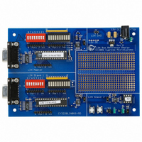
CY3220LINBUS-RD Cypress Semiconductor Corp, CY3220LINBUS-RD Datasheet - Page 43

CY3220LINBUS-RD
Manufacturer Part Number
CY3220LINBUS-RD
Description
KIT REF DESIGN LIN BUS
Manufacturer
Cypress Semiconductor Corp
Series
PSoC®r
Datasheet
1.CY3220LINBUS-RD.pdf
(64 pages)
Specifications of CY3220LINBUS-RD
Main Purpose
Interface, LIN
Embedded
Yes, MCU, 8-Bit
Utilized Ic / Part
CY8C27143, CY8C27443
Processor To Be Evaluated
CY8C27143-24PXI and CY8C27443-24PXI
Interface Type
RS-232
Lead Free Status / RoHS Status
Contains lead / RoHS non-compliant
Lead Free Status / RoHS Status
Lead free / RoHS Compliant, Contains lead / RoHS non-compliant
Other names
428-1926
LIN Bus 2.0 Reference Design
Table 4-6. TxInterrupt
Table 4-7. TxBitTimerInterrupt
Table 4-8. Other Functions
The overall CPU overhead for a frame is calculated by add-
ing all the time components for a frame and then finding the
fraction on the total frame time. Remember, this method only
provides the overall overhead. At some instances, the CPU
overhead is quite high, especially inside the GPIO ISR. As a
result, calculate the CPU overhead taking into account the
time between successive interrupts and the time taken
inside any particular branch of the GPIO ISR.
4.8.2
These calculations are based upon a baud rate of 19.2 kbps
and CPU speed of 24 MHz. For lower baud rates, the CPU
overhead is less.
Example 1: A frame of 1 byte being received.
Total time for Break/Synch = 224 µS.
Known ID received, RX initialized = 16 µS.
1 byte to received = 7 µS.
Frame reception complete (checksum received) = 73 µS.
Total time = 320 µS.
Total bits in frame = 54.
Total frame time = 1.4 * 54 * 1/19.2K = 3.93 mS.
Overall CPU overhead = 320 µS / 3.93 mS = 8.14%.
For calculation, the worst case frame length of 1 byte was
used. For an 8-byte frame, the overhead is reduced to 4%.
Example 2: A frame of 1 byte being transmitted
October 25, 2006
1
2
1
Sl. No.
1
2
3
Sl. No.
Sl. No.
LoadSynchroReceptionConfiguration 790
LoadDataReceptionConfiguration
LoadDataTransmissionConfiguration
When a byte has been sent
When last byte has been sent
All bytes transmitted
Calculation of CPU Overhead Over
a Frame
Stage
Stage
Stage
1200
166
130
No. Of Cycles
No. Of Cycles
768
153
No. Of Cycles Time(
Cypress Semiconductor – Rev. **
6.92
5.42
Time(
50.00
Time(
32.92
32.00
6.38
µ
µ
µ
S)
S)
S)
Total time for Break/Synch = 224 µS.
Known ID received, TX initialized = 39 µS.
2 bytes to be transmitted (1 byte + checksum) = 2 * Single
byte transmitted = 14 µS.
All bytes transmitted = 50 µS.
Total time = 327 µS.
Total bits in frame = 54.
Total frame time = 1.4 * 54 * 1/19.2K = 3.9 3 mS.
Overall CPU overhead = 327 µS / 3.93 mS = 8.32%.
For calculation, the worst case frame length of 1 byte was
used. For an 8-byte frame, the overhead is reduced to 4%.
4.8.3
This is the maximum latency the LIN node causes in an
application. Using the information listed in the tables section
4.8.1, the maximum time taken inside the ISR is in the GPIO
ISR when the fourth falling edge was received and this value
is 150 µS. Take this value into consideration when the inter-
rupts of the main application are designed or analyzed.
Maximum Interrupt Latency
4. Slave Design IP
41


