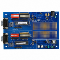
CY3220LINBUS-RD Cypress Semiconductor Corp, CY3220LINBUS-RD Datasheet - Page 20

CY3220LINBUS-RD
Manufacturer Part Number
CY3220LINBUS-RD
Description
KIT REF DESIGN LIN BUS
Manufacturer
Cypress Semiconductor Corp
Series
PSoC®r
Datasheet
1.CY3220LINBUS-RD.pdf
(64 pages)
Specifications of CY3220LINBUS-RD
Main Purpose
Interface, LIN
Embedded
Yes, MCU, 8-Bit
Utilized Ic / Part
CY8C27143, CY8C27443
Processor To Be Evaluated
CY8C27143-24PXI and CY8C27443-24PXI
Interface Type
RS-232
Lead Free Status / RoHS Status
Contains lead / RoHS non-compliant
Lead Free Status / RoHS Status
Lead free / RoHS Compliant, Contains lead / RoHS non-compliant
Other names
428-1926
3. Master Design IP
3.3.5.3
In the Data Reception Configuration, the bit time counter is
configured to generate an interrupt every five bit times.
Inside this ISR, a timeout counter is decremented by five.
This timeout counter is initialized by the l_sch_tick function
according to the number of data present in the frame. In a
normal frame transaction, the frame is completed before this
counter becomes zero. However, if the slave stops transmit-
ting in the middle of the frame for any reason, and the time-
out counter becomes zero, a timeout is detected, the
SLAVE_NOT_RESPONDING error flag is set and the Syn-
chro Break Configuration is loaded.
3.4
Lin20CoreAPI.asm: This file has all the functions for the
LIN core API.
Lin20NodeConfiguration.asm: This file has all the func-
tions for the node configuration.
Lin20PhysicalLayer.asm: This file has all the code related
to the proper operation of the LIN firmware. This file has all
the ISRs described in section 3.3,
RamVariables.asm: This file has all RAM variable alloca-
tions.
SignalTable.asm: This file has the Message table and the
Protected ID table. This file must be modified according to
the LDF.
ScheduleTable.asm: This file has the Schedule tables used
in the master design. This file must be modified according to
the LDF.
LinPowerManagement.c: This file has the functions that
are required for the go to sleep and wakeup operations of
the LIN master.
NodeConfigUtilities.c: This file has some functions that
can be used for node configuration functions.
3.5
Lin20CoreAPI.h: This file has all the function prototypes for
the Lin20CoreAPI.asm file.
Lin20NodeConfiguration.h: This file has all the function
prototypes for the Lin20Nodeconfiguration.asm file.
Lin20Defines.h: This file has the variable types defined in
the LIN specifications.
Lin20Master.h: This file has the definitions of different con-
stants and flags used in the firmware.
LinPowerManagement.h: This file has the function proto-
types for the LinPowerManagement.c file.
NodeConfigUtilities.h: This file has the function prototypes
for the NodeConfigUtilities.c file.
18
Source Code Files
Header Files
Data Reception Configuration
Firmware on page
Cypress Semiconductor – Rev. **
17.
SignalTable.h: This file has declarations of the signal buff-
ers and frame names used in the SignalTable.asm file.
ScheduleTable.h: This file has the declarations of the
Schedule table names used in the ScheduleTable.asm file.
Lin20Master.inc: This file has the definitions of all the con-
stants and flags used by the Lin20PhysicalLayer.asm file.
Of all source code and header files, you must modify the fol-
lowing files according to the LDF.
■
■
■
■
■
3.6
Follow these steps to create a LIN master PSoC project
using the Design IP.
3.6.1
There are two ways to import the design. One is to create a
new project in PSoC Designer and use the design-based
project option. The other is to create a project and then
import the design using the Design Browser. The recom-
mended method is to create a new design-based project.
1. Select
2. Select the directory in which to create the project files.
3. Select the directory and name for a project.
4. The Design Browser opens. The Design Browser has
5. Below the Design Browser window, there are two radio
6. Below this there are two windows, “Resolve name con-
Lin20Master.inc
SignalTable.asm
SignalTable.h
ScheduleTable.asm
ScheduleTable.h
File >> New Project >> Create Design-Based Project.
two windows. The window on the left side is the Design
Browser itself where you select the design. The window
on the right side shows the data sheet for the selected
design. On the top of the Design Browser window there
are two radio buttons that select between “Browse File
System” and “Select From Design Catalog.” Click the
"Browse File System" option. Navigate to the "\Design
IP\Lin2.0 Master" directory on the CD, and open the
folder corresponding to the device that you want to use.
Then select the .cfg file in this directory. Now the data
sheet window on the right shows the data sheet of the
LIN master design.
buttons, “Overwrite configurations with same name” and
“Resolve configuration name conflicts.” Use these
options when importing a design into an already-existing
project and if some of the configurations from the exist-
ing project have the same name as that of the imported
design.
flicts” and the “Specify base configuration.” The “Specify
base configuration” window has the Synchro Break Con-
figuration, Data Transmission Configuration and Data
Reception Configurations listed. Do not select any of
these options.
Creating a Project Using the
Design IP
Importing the Design
LIN Bus 2.0 Reference Design
October 25, 2006


