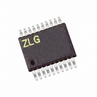
Z8F0413HH005EG Zilog, Z8F0413HH005EG Datasheet - Page 134

Z8F0413HH005EG
Manufacturer Part Number
Z8F0413HH005EG
Description
IC ENCORE MCU FLASH 4K 20SSOP
Manufacturer
Zilog
Series
Encore!® XP®r
Datasheet
1.Z8F0223SB005SG.pdf
(247 pages)
Specifications of Z8F0413HH005EG
Core Processor
Z8
Core Size
8-Bit
Speed
5MHz
Connectivity
IrDA, UART/USART
Peripherals
Brown-out Detect/Reset, LED, POR, PWM, WDT
Number Of I /o
16
Program Memory Size
4KB (4K x 8)
Program Memory Type
FLASH
Ram Size
1K x 8
Voltage - Supply (vcc/vdd)
2.7 V ~ 3.6 V
Oscillator Type
Internal
Operating Temperature
-40°C ~ 105°C
Package / Case
20-SSOP
For Use With
770-1002 - ISP 4PORT ZILOG Z8 ENCORE! MCU269-4643 - KIT DEV Z8 ENCORE XP 28-PIN269-4630 - DEV KIT FOR Z8 ENCORE 8K/4K269-4629 - KIT DEV Z8 ENCORE XP 28-PIN269-4628 - KIT DEV Z8 ENCORE XP 8-PIN
Lead Free Status / RoHS Status
Lead free / RoHS Compliant
Eeprom Size
-
Data Converters
-
Other names
269-4108
Z8F0413HH005EG
Z8F0413HH005EG
- Current page: 134 of 247
- Download datasheet (4Mb)
Table 73. ADC Control/Status Register 1 (ADCCTL1)
Table 74. ADC Data High Byte Register (ADCD_H)
BITS
FIELD
RESET
R/W
ADDR
BITS
FIELD
RESET
R/W
ADDR
PS024314-0308
ADC Control/Status Register 1
ADC Data High Byte Register
REFSELH
R/W
R
7
1
7
X
The second ADC Control register contains the voltage reference level selection bit.
REFSELH—Voltage Reference Level Select High Bit; in conjunction with the Low bit
(REFSELL) in
reference; the following details the effects of {REFSELH, REFSELL}; this reference is
independent of the Comparator reference
00= Internal Reference Disabled, reference comes from external pin
01= Internal Reference set to 1.0 V
10= Internal Reference set to 2.0 V (default)
The ADC Data High Byte register contains the upper eight bits of the ADC output. The
output is an 11-bit two’s complement value. During a single-shot conversion, this value is
invalid. Access to the ADC Data High Byte register is read-only. Reading the ADC Data
High Byte register latches data in the ADC Low Bits register.
ADCDH—ADC Data High Byte
This byte contains the upper eight bits of the ADC output. These bits are not valid during a
single-shot conversion. During a continuous conversion, the most recent conversion out-
put is held in this register. These bits are undefined after a Reset.
R/W
X
R
6
0
6
ADC Control Register
R/W
R
X
5
0
5
R/W
X
R
4
0
4
ADCDH
0, this determines the level of the internal voltage
F71H
F72H
Reserved
R/W
R
X
3
0
3
Z8 Encore! XP
R/W
X
R
2
0
2
Product Specification
Analog-to-Digital Converter
R/W
R
X
1
0
1
®
F0823 Series
R/W
X
R
0
0
0
124
Related parts for Z8F0413HH005EG
Image
Part Number
Description
Manufacturer
Datasheet
Request
R

Part Number:
Description:
Communication Controllers, ZILOG INTELLIGENT PERIPHERAL CONTROLLER (ZIP)
Manufacturer:
Zilog, Inc.
Datasheet:

Part Number:
Description:
KIT DEV FOR Z8 ENCORE 16K TO 64K
Manufacturer:
Zilog
Datasheet:

Part Number:
Description:
KIT DEV Z8 ENCORE XP 28-PIN
Manufacturer:
Zilog
Datasheet:

Part Number:
Description:
DEV KIT FOR Z8 ENCORE 8K/4K
Manufacturer:
Zilog
Datasheet:

Part Number:
Description:
KIT DEV Z8 ENCORE XP 28-PIN
Manufacturer:
Zilog
Datasheet:

Part Number:
Description:
DEV KIT FOR Z8 ENCORE 4K TO 8K
Manufacturer:
Zilog
Datasheet:

Part Number:
Description:
CMOS Z8 microcontroller. ROM 16 Kbytes, RAM 256 bytes, speed 16 MHz, 32 lines I/O, 3.0V to 5.5V
Manufacturer:
Zilog, Inc.
Datasheet:

Part Number:
Description:
Low-cost microcontroller. 512 bytes ROM, 61 bytes RAM, 8 MHz
Manufacturer:
Zilog, Inc.
Datasheet:

Part Number:
Description:
Z8 4K OTP Microcontroller
Manufacturer:
Zilog, Inc.
Datasheet:

Part Number:
Description:
CMOS SUPER8 ROMLESS MCU
Manufacturer:
Zilog, Inc.
Datasheet:

Part Number:
Description:
SL1866 CMOSZ8 OTP Microcontroller
Manufacturer:
Zilog, Inc.
Datasheet:

Part Number:
Description:
SL1866 CMOSZ8 OTP Microcontroller
Manufacturer:
Zilog, Inc.
Datasheet:

Part Number:
Description:
OTP (KB) = 1, RAM = 125, Speed = 12, I/O = 14, 8-bit Timers = 2, Comm Interfaces Other Features = Por, LV Protect, Voltage = 4.5-5.5V
Manufacturer:
Zilog, Inc.
Datasheet:

Part Number:
Description:
Manufacturer:
Zilog, Inc.
Datasheet:


