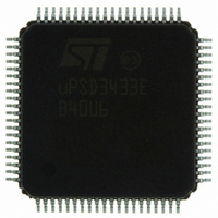
UPSD3433EB40U6 STMicroelectronics, UPSD3433EB40U6 Datasheet - Page 64

UPSD3433EB40U6
Manufacturer Part Number
UPSD3433EB40U6
Description
MCU 8BIT 8032 128KB FLASH 80TQFP
Manufacturer
STMicroelectronics
Series
µPSDr
Datasheet
1.UPSD3434EB40T6.pdf
(293 pages)
Specifications of UPSD3433EB40U6
Core Processor
8032
Core Size
8-Bit
Speed
40MHz
Connectivity
I²C, IrDA, SPI, UART/USART, USB
Peripherals
LVD, POR, PWM, WDT
Number Of I /o
46
Program Memory Size
160KB (160K x 8)
Program Memory Type
FLASH
Ram Size
8K x 8
Voltage - Supply (vcc/vdd)
3 V ~ 5.5 V
Data Converters
A/D 8x10b
Oscillator Type
Internal
Operating Temperature
-40°C ~ 85°C
Package / Case
80-TQFP, 80-VQFP
For Use With
497-5518 - EVAL BOARD RFID READER497-5046 - KIT TOOL FOR ST7/UPSD/STR7 MCU
Lead Free Status / RoHS Status
Lead free / RoHS Compliant
Eeprom Size
-
Other names
497-5660
Available stocks
Company
Part Number
Manufacturer
Quantity
Price
Company:
Part Number:
UPSD3433EB40U6
Manufacturer:
STMicroelectronics
Quantity:
10 000
- Current page: 64 of 293
- Download datasheet (5Mb)
Power saving modes
15.2
15.3
Note:
64/293
Power-down Mode
Power-down Mode will halt the 8032 core and all MCU peripherals (Power-down Mode
blocks MCU_CLK, USB_CLK, and PERIPH_CLK). This is the lowest power state for the
MCU Module. When the PSD Module is also placed in Power-down mode, the lowest total
current consumption for the combined die is achieved for the uPSD34xx. See
Section 28.1.16: Power management on page 191
how to also place the PSD Module in Power-down mode. The sequence of 8032 instructions
is important when placing both modules into Power-down Mode.
The instruction that sets the PD Bit in the SFR named PCON
last instruction executed prior to the MCU Module going into Power-down Mode. Once in
Power-down Mode, the on-chip oscillator circuitry and all clocks are stopped. The SFRs,
DATA, IDATA, and XDATA are preserved.
Power-down Mode is terminated only by a reset from the supervisor, originating from the
RESET_IN_ pin, the Low-Voltage Detect circuit (LVD), or a JTAG Debug reset command.
Since the clock to the WTD is not active during Power-down mode, it is not possible for the
supervisor to generate a WDT reset.
Table 24 on page 65
Power-down Modes on the MCU Module.
MCU address, data, and control signals during these modes.
Reduced Frequency Mode
The 8032 MCU consumes less current when operating at a lower clock frequency. The MCU
can reduce its own clock frequency at run-time by writing to three bits, CPUPS[2:0], in the
SFR named CCON0 described in
clock frequency (f
division range is from 1/2 to 1/2048, and the resulting frequency is f
This MCU clock division does not affect any of the peripherals, except for the WTD. The
clock driving the WTD is the same clock driving the 8032 MCU core as shown in
on page
MCU firmware may reduce the MCU clock frequency at run-time to consume less current
when performing tasks that are not time critical, and then restore full clock frequency as
required to perform urgent tasks.
Returning to full clock frequency is done automatically upon an MCU interrupt, if the CPUAR
Bit in the SFR named CCON0 is set (the interrupt will force CPUPS[2:0] = 000). This is an
excellent way to conserve power using a low frequency clock until an event occurs that
requires full performance. See
See the DC Specifications at the end of this document to estimate current consumption
based on the MCU clock frequency.
Some of the bits in the PCON SFR shown in
control.
61.
OSC
summarizes the status of I/O pins and peripherals during Idle and
) coming in from the external crystal or oscillator device. The clock
Table 22 on page 62
Table 22 on page
Table 25 on page 65
Table 26 on page 66
in the PSD Module section for details on
for details on CPUAR.
62. These bits effectively divide the
(Table 26 on page
shows the state of 8032
are not related to power
MCU
.
66) is the
uPSD34xx
Figure 14
Related parts for UPSD3433EB40U6
Image
Part Number
Description
Manufacturer
Datasheet
Request
R

Part Number:
Description:
MCU 8BIT 8032 128KB FLASH 80TQFP
Manufacturer:
STMicroelectronics
Datasheet:

Part Number:
Description:
MCU 8BIT 8032 128KB FLASH 52TQFP
Manufacturer:
STMicroelectronics
Datasheet:

Part Number:
Description:
STMicroelectronics [RIPPLE-CARRY BINARY COUNTER/DIVIDERS]
Manufacturer:
STMicroelectronics
Datasheet:

Part Number:
Description:
STMicroelectronics [LIQUID-CRYSTAL DISPLAY DRIVERS]
Manufacturer:
STMicroelectronics
Datasheet:

Part Number:
Description:
BOARD EVAL FOR MEMS SENSORS
Manufacturer:
STMicroelectronics
Datasheet:

Part Number:
Description:
NPN TRANSISTOR POWER MODULE
Manufacturer:
STMicroelectronics
Datasheet:

Part Number:
Description:
TURBOSWITCH ULTRA-FAST HIGH VOLTAGE DIODE
Manufacturer:
STMicroelectronics
Datasheet:

Part Number:
Description:
Manufacturer:
STMicroelectronics
Datasheet:

Part Number:
Description:
DIODE / SCR MODULE
Manufacturer:
STMicroelectronics
Datasheet:

Part Number:
Description:
DIODE / SCR MODULE
Manufacturer:
STMicroelectronics
Datasheet:

Part Number:
Description:
Search -----> STE16N100
Manufacturer:
STMicroelectronics
Datasheet:

Part Number:
Description:
Search ---> STE53NA50
Manufacturer:
STMicroelectronics
Datasheet:


