DS87C550-QCL+ Maxim Integrated Products, DS87C550-QCL+ Datasheet - Page 13
DS87C550-QCL+
Manufacturer Part Number
DS87C550-QCL+
Description
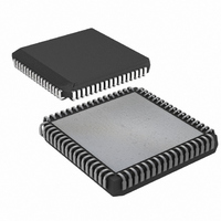
IC MCU EPROM ADC/PWM HS 68-PLCC
Manufacturer
Maxim Integrated Products
Series
87Cr
Datasheet
1.DS87C550-QNL.pdf
(49 pages)
Specifications of DS87C550-QCL+
Core Processor
8051
Core Size
8-Bit
Speed
33MHz
Connectivity
EBI/EMI, SIO, UART/USART
Peripherals
Power-Fail Reset, PWM, WDT
Number Of I /o
55
Program Memory Size
8KB (8K x 8)
Program Memory Type
OTP
Ram Size
1K x 8
Voltage - Supply (vcc/vdd)
4.5 V ~ 5.5 V
Data Converters
A/D 6x10b
Oscillator Type
External
Operating Temperature
0°C ~ 70°C
Package / Case
68-LCC, 68-PLCC
Lead Free Status / RoHS Status
Lead free / RoHS Compliant
Eeprom Size
-


that may not have fast RAM in place. Internal SRAM access is always at full speed regardless of the
Stretch setting. When maximum speed is desired, software should select a Stretch value of 0. When using
very slow RAM or peripherals, the application software can select a larger Stretch value. Note that this
affects data memory accesses only and that there is no way to slow the accesses to program memory other
than to use a slower crystal (or external clock).
The specific timing of the variable speed Stretch MOVX is provided in the Electrical Specifications
section of this data sheet. Table 4 shows the resulting MOVX instruction timing and the read or write
strobe widths for each Stretch value.
DATA MEMORY CYCLE STRETCH VALUES Table 4
Dual Data Pointer With Inc/Dec
The DS87C550 contains several new, unique features that are associated with the Data Pointer register. In
the original 8051 architecture, the DPTR was a 16-bit value that was used to address off-chip data RAM
or peripherals. To improve the efficiency of data moves, the DS87C550 contains two Data Pointer
registers (DPTR0 and DPTR1). By loading one DPTR with the source address and the other with the
destination address, block data moves can be made much more efficient. Since DPTR0 is located at the
same address as the single DPTR in the original 8051 architecture, code written for the original
architecture will operate normally on the DS87C550 with no modification necessary.
The second data pointer, DPTR1 is located at the next two register locations (up from DPTR0) and is
selected using the data pointer select bit SEL (DPS.0). If SEL = 0, then DPTR0 is the active data pointer.
Conversely, if SEL = 1, then DPTR1 is the active data pointer. Any instruction that references the DPTR
(ex. MOVX A, @ DPTR) refers to the active data pointer as determined by the SEL bit. Since the bit
adjacent to SEL in the DPS register is not used, the fastest means of changing the SEL (and thereby
changing the active data pointer) is with an INC instruction. Each INC DPS Instruction will toggle the
active data pointer.
Unlike the standard 8051, the DS87C550 has the ability to decrement as well as increment the data
pointers without additional instructions. When the INC DPTR instruction is executed, the active DPTR is
incremented or decremented according to the ID1, ID0 (DPS.7-6), and SEL (DPS.0) bits as shown. The
inactive DPTR is not affected.
ID1
X
X
0
1
ID0
X
X
0
1
M2
0
0
0
0
1
1
1
1
CKCON.2-0
SEL
0
1
0
1
M1
0
0
1
1
0
0
1
1
RESULT OF INC DPTR
INCREMENT DPTR0
DECREMENT DPTR0
INCREMENT DPTR1
DECREMENT DPTR1
M0
0
1
0
1
0
1
0
1
MOVX MACHINE
3 (default external)
2 (forced internal)
CYCLES
10
11
12
4
5
9
13 of 49
RD
IN MACHINE CYCLES
OR
WR
STROBE WIDTH
0.5
1
2
3
4
5
6
7
Related parts for DS87C550-QCL+
Image
Part Number
Description
Manufacturer
Datasheet
Request
R

Part Number:
Description:
IC MCU EPROM ADC/PWM HS 68-PLCC
Manufacturer:
Maxim Integrated Products
Datasheet:

Part Number:
Description:
Eprom High-speed Microcontroller With Adc And Pwm
Manufacturer:
Maxim Integrated Products, Inc.
Datasheet:

Part Number:
Description:
MAX7528KCWPMaxim Integrated Products [CMOS Dual 8-Bit Buffered Multiplying DACs]
Manufacturer:
Maxim Integrated Products
Datasheet:
Part Number:
Description:
Single +5V, fully integrated, 1.25Gbps laser diode driver.
Manufacturer:
Maxim Integrated Products
Datasheet:
Part Number:
Description:
Single +5V, fully integrated, 155Mbps laser diode driver.
Manufacturer:
Maxim Integrated Products
Datasheet:
Part Number:
Description:
VRD11/VRD10, K8 Rev F 2/3/4-Phase PWM Controllers with Integrated Dual MOSFET Drivers
Manufacturer:
Maxim Integrated Products
Datasheet:
Part Number:
Description:
Highly Integrated Level 2 SMBus Battery Chargers
Manufacturer:
Maxim Integrated Products
Datasheet:
Part Number:
Description:
Current Monitor and Accumulator with Integrated Sense Resistor; ; Temperature Range: -40°C to +85°C
Manufacturer:
Maxim Integrated Products
Part Number:
Description:
TSSOP 14/A°/RS-485 Transceivers with Integrated 100O/120O Termination Resis
Manufacturer:
Maxim Integrated Products
Part Number:
Description:
TSSOP 14/A°/RS-485 Transceivers with Integrated 100O/120O Termination Resis
Manufacturer:
Maxim Integrated Products
Part Number:
Description:
QFN 16/A°/AC-DC and DC-DC Peak-Current-Mode Converters with Integrated Step
Manufacturer:
Maxim Integrated Products
Part Number:
Description:
TDFN/A/65V, 1A, 600KHZ, SYNCHRONOUS STEP-DOWN REGULATOR WITH INTEGRATED SWI
Manufacturer:
Maxim Integrated Products
Part Number:
Description:
Integrated Temperature Controller f
Manufacturer:
Maxim Integrated Products
Part Number:
Description:
SOT23-6/I°/45MHz to 650MHz, Integrated IF VCOs with Differential Output
Manufacturer:
Maxim Integrated Products
Part Number:
Description:
SOT23-6/I°/45MHz to 650MHz, Integrated IF VCOs with Differential Output
Manufacturer:
Maxim Integrated Products