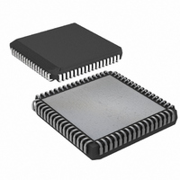
DS87C550-QCL+ Maxim Integrated Products, DS87C550-QCL+ Datasheet - Page 24

DS87C550-QCL+
Manufacturer Part Number
DS87C550-QCL+
Description
IC MCU EPROM ADC/PWM HS 68-PLCC
Manufacturer
Maxim Integrated Products
Series
87Cr
Datasheet
1.DS87C550-QNL.pdf
(49 pages)
Specifications of DS87C550-QCL+
Core Processor
8051
Core Size
8-Bit
Speed
33MHz
Connectivity
EBI/EMI, SIO, UART/USART
Peripherals
Power-Fail Reset, PWM, WDT
Number Of I /o
55
Program Memory Size
8KB (8K x 8)
Program Memory Type
OTP
Ram Size
1K x 8
Voltage - Supply (vcc/vdd)
4.5 V ~ 5.5 V
Data Converters
A/D 6x10b
Oscillator Type
External
Operating Temperature
0°C ~ 70°C
Package / Case
68-LCC, 68-PLCC
Lead Free Status / RoHS Status
Lead free / RoHS Compliant
Eeprom Size
-
PULSE WIDTH MODULATION
The DS87C550 contains four independent 8-bit pulse width modulator (PWMs) functions each with
independently selectable clock sources. For more precise modulation operations, two 8-bit PWM
functions (PWM0 & PWM1 and/or PWM2 & PWM3) can be cascaded together to form a 16-bit PWM
function.
The PWM function is divided into three major blocks: a clock prescaler, a clock generator, and a pulse
generator. A single prescaler provides selectable clocks of different frequencies to each of the four clock
generator blocks. Each clock generator is an 8-bit reloadable counter that determines the repetition rate
(frequency) of its associated PWM. Each pulse generator PWM block is an 8-bit timer clocked by the
clock generator’s output. When this timer reaches zero, the output of the PWM is set to 1. When the timer
reaches the user selected PWM match value stored in SFR PWMx, the PWM output is cleared to 0. In
this way, the frequency and duty cycle of the PWM is varied under software control.
PWM PRESCALER
The prescaler block of the PWM function accepts as a clock input the system clock provided to the CPU
(and other peripherals), and divides it by 1, 4, 16, and 64. Each of these clocks is available at the output
of the prescaler, and is provided to all four of the PWM clock generator blocks. The actual clock used by
the clock generator block is dependant on the setting of SFR bits PWxS2:0 (where x is the PWM channel
number 0-3) located in the PW01CS or PW23CS registers. In addition to selecting one of the prescaler’s
CPU clock divided outputs, setting PWxS2 to a 1 allows an external clock to be used as an input to the
clock generators. The external clocks are input on device pins PWMC0 (P6.4 for PWM0 or PWM1) or
PWMC1 (P6.5 for PWM2 or PWM3). Like all other inputs to the 8051, these inputs are synchronized by
sampling them using the internal machine cycle clock. Therefore these inputs must be of sufficient
duration for the clock to sample them properly (i.e., 2 machine cycles). The complete functionality of the
clock selection SFR bits is as follows:
Machine Cycle_Clock/1
Machine Cycle_Clock/4
Machine Cycle_Clock/16
Machine Cycle_Clock/64
PWMCx (external)
In determining the exact frequency output of the prescaler, it is important to note that the machine cycle
clock provided to the prescaler is also software-selectable. The machine cycle clock can be the crystal (or
oscillator frequency) divided by 1, 2, 4, or 1024 as determined by the CD1:0 and the 4X/
Clock Divide Control section for details).
PWM CLOCK GENERATOR
The clock generator blocks of the PWM modules are pre-loaded by software with an 8-bit value, and this
value determines the frequency or repetition rate of the PWM function. A value of 0 causes the selected
output of the prescaler to be passed directly to the pulse generator function (i.e., divide by 1). A value of
FFh passes a clock to the pulse generator function that is the selected prescaler output divided by 256. In
general, the clock generators provide a divide by N+1 selectable repetition rate (i.e., frequency) for their
PWM channel.
Prescaler Output
PWxS2:0
000
001
010
011
1xx
24 of 49
2X
SFR bits (see


