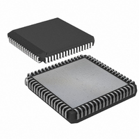
DS87C550-QCL+ Maxim Integrated Products, DS87C550-QCL+ Datasheet - Page 21

DS87C550-QCL+
Manufacturer Part Number
DS87C550-QCL+
Description
IC MCU EPROM ADC/PWM HS 68-PLCC
Manufacturer
Maxim Integrated Products
Series
87Cr
Datasheet
1.DS87C550-QNL.pdf
(49 pages)
Specifications of DS87C550-QCL+
Core Processor
8051
Core Size
8-Bit
Speed
33MHz
Connectivity
EBI/EMI, SIO, UART/USART
Peripherals
Power-Fail Reset, PWM, WDT
Number Of I /o
55
Program Memory Size
8KB (8K x 8)
Program Memory Type
OTP
Ram Size
1K x 8
Voltage - Supply (vcc/vdd)
4.5 V ~ 5.5 V
Data Converters
A/D 6x10b
Oscillator Type
External
Operating Temperature
0°C ~ 70°C
Package / Case
68-LCC, 68-PLCC
Lead Free Status / RoHS Status
Lead free / RoHS Compliant
Eeprom Size
-
EMI REDUCTION
One of the major contributors to radiated noise in an 8051-based system is the toggling of ALE. The
DS87C550 allows software to disable ALE when not used by setting the ALEOFF (PMR.2) bit to a 1.
When ALEOFF = 1, ALE will still toggle during an off-chip MOVX. However, ALE will remain inactive
when performing on-chip memory access. The default state is ALEOFF = 0 so ALE normally toggles at a
frequency of XTAL/4.
PERIPHERAL OVERVIEW
The DS87C550 provides several of the most commonly needed peripheral functions in microcomputer-
based systems. New functions include a second serial port, power-fail reset, power-fail interrupt flag, and
a programmable watchdog timer. In addition, the DS87C550 contains an analog-to-digital converter and
four channels of pulse width modulation for industrial control and measurement applications. Each of
these peripherals is described below. More details are available in the High-Speed Microcontroller User's
Guide: DS87C550 Supplement.
SERIAL PORTS
The DS87C550 provides a serial port (UART) that is identical to the 80C52. In addition, it includes a
second hardware serial port that is a full duplicate of the standard one. This port optionally uses pins P1.6
(RXD1) and P1.7 (TXD1). It has duplicate control functions included in new SFR locations.
Both ports can operate simultaneously but can be at different baud rates or even in different modes. The
second serial port has similar control registers (SCON1, SBUF1) to the original. The new serial port can
only use Timer 1 for timer generated baud rates.
Control for serial port 0 is provided by the SCON0 register while its I/O buffer is SBUF0. The registers
SCON1 and SBUF1 provide the same functions for the second serial port. A full description of the use
and operation of both serial ports may be found in the High-Speed Microcontroller User's Guide,
available from the Maxim website.
ANALOG TO DIGITAL CONVERTER
The DS87C550 contains a 10-bit successive approximation analog-to-digital converter. This converter
provides eight multiplexed channels of analog input using an external voltage reference for the
conversion process.
Before using the A/D converter, the converter must be configured by performing two actions:
1. The user must set the ADON bit (ADCON1.1). This enables the A/D converter. This bit defaults to 0
2. In addition, the user must set the ADRS bit (PWMADR.7) to enable the external voltage reference
A/D CONVERTER INPUTS
The A/D converter of the DS87C550 provides eight channels of analog input on device pins ADC7
through ADC0 (P5.7-P5.0). The signals on these pins are input into an analog multiplexer. The magnitude
(and polarity) of these signals is limited by the external reference (A
converter. See the DC electrical characteristics section of this data sheet for more details.
following a reset, disabling the A/D converter to conserve power.
pins. This bit defaults to 0 following a reset, disabling the A/D converter voltage reference pins.
21 of 49
VREF+
, A
VREF-
) voltages used by the


