DS87C550-QCL+ Maxim Integrated Products, DS87C550-QCL+ Datasheet - Page 26
DS87C550-QCL+
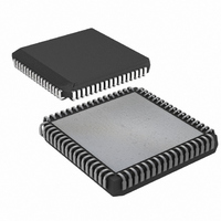
Manufacturer Part Number
DS87C550-QCL+
Description
IC MCU EPROM ADC/PWM HS 68-PLCC
Manufacturer
Maxim Integrated Products
Series
87Cr
Datasheet
1.DS87C550-QNL.pdf
(49 pages)
Specifications of DS87C550-QCL+
Core Processor
8051
Core Size
8-Bit
Speed
33MHz
Connectivity
EBI/EMI, SIO, UART/USART
Peripherals
Power-Fail Reset, PWM, WDT
Number Of I /o
55
Program Memory Size
8KB (8K x 8)
Program Memory Type
OTP
Ram Size
1K x 8
Voltage - Supply (vcc/vdd)
4.5 V ~ 5.5 V
Data Converters
A/D 6x10b
Oscillator Type
External
Operating Temperature
0°C ~ 70°C
Package / Case
68-LCC, 68-PLCC
Lead Free Status / RoHS Status
Lead free / RoHS Compliant
Eeprom Size
-


DS87C550 EPROM High-Speed Microcontroller with ADC and PWM
a 1, a new 16-bit PWM1 function is formed from PWM2 (LSB) and PWM3 (MSB). Since each pair of
PWMs can be independently configured into a 16-bit arrangement, the user has the option of having four
8-bit PWM functions, two 8-bit PWM functions and a 16-bit PWM function, or two 16-bit PWM
functions.
In 16-bit PWM mode, the prescaler operates exactly as it did in 8-bit mode. Its outputs are available to all
four clock generator blocks. However in 16-bit mode, the clock generators for 8-bit PWM1 and PWM3
are not functional. The clock for 16-bit PWM0 function is provided by the clock generator for 8-bit
PWM0 and the clock for 16-bit PWM1 function is provided by the clock generator for 8-bit PWM2. The
SFR bits PW0EN (clock generator enable) and PW0S2:0 (clock select bits) provide the programmable
clock controls for 16-bit PWM channel 0, and bits PW2EN and PW2S2:0 provide the programmable
clock controls for 16-bit PWM channel 1. The clock divisor values for the 16-bit PWM operating
frequency are contained in the PW0FG and PW2FG registers for 16-bit PWM0 and PWM1
(respectively). Note that these registers remain 8-bit values so the clock division remains the same for 16-
bit and 8-bit operation.
When in 16-bit mode, the two 8-bit pulse generator timers are concatenated together forming a 16-bit
timer. Therefore the pulse generator section of a 16-bit PWM channel has a repetition rate of the input
clock divided by 65,536. As in 8-bit mode when the counter reaches 0, the output of the 16-bit PWM
channel is set (i.e., logic 1), and when it reaches the pre-loaded match value it is cleared (i.e., logic 0).
GENERAL PURPOSE TIMERS/COUNTERS
The DS87C550 contains three general-purpose timer/ counters. Timers 0 and 1 are standard 8051 16-bit
timer/counters with three modes of operation. Each of these devices can be used as a 13-bit timer/counter,
16-bit timer/counter or 8-bit timer/counter with auto-reload. Timer 0 can also operate as two 8-bit timer
counters. Each timer can also be used as a counter of external pulses on the corresponding T0 or T1 pin.
The mode of operation is controlled by the Timer Mode (TMOD) register. Each timer/counter consists of
a 16-bit register in 2 bytes, which can be found in the SFR map as TL0, TH0, TL1, and TH1. These two
timers are enabled by the Timer Control (TCON) register. A complete description of use and operation of
these timers may be found in the High-Speed Microcontroller User's Guide.
Timer 2 is a true 16-bit timer/counter with several additional features as compared to timers 1 and 0. With
a 16-bit reload register (RLOADL, RLOADH), it provides up/down auto-reload timer/counters and timer
output clock generation. Timer 2 also supports a capture/compare function. This new feature provides
additional timing control capabilities for real-time applications with less CPU intervention. A more
detailed description of this capture/compare feature is provided below.
TIMER 2
The selection of a timer or counter function is controlled by the C/
(T2CON.1) bit When C/
is set to
T2
T2
1, Timer 2 acts as a counter where it counts 1 to 0 transitions on the T2 pin. When C/
is cleared to a 0,
T2
Timer 2 functions as a timer where it counts the system clock as determined by the T2M bit (CKCON.5)
and the clock divide control bits CD1, CD0 (PMR.7:6) and the 4X/
(PMR.3) bit. A prescaler is used to
2X
further divide the input clock by a programmable ratio. The prescaler value is programmable to divide by
1, 2, 4, and 8 as defined by the T2P1 and T2P0 (T2SEL.1:0) bits. Timer 2 is enabled by setting bit TR2
(T2CON.2) to a 1, and disabled by clearing it to a 0.
When the LSB of timer/counter 2 (TL2) overflows, flag TF2B (T2SEL.4) is set, and flag TF2 (T2CON.7)
is set when the high byte (TH2) overflows. Setting flag TF2 also sets flag TF2B. Even though only one
interrupt is available for Timer 2, either or both of these overflows can be programmed to request an
26 of 49
Related parts for DS87C550-QCL+
Image
Part Number
Description
Manufacturer
Datasheet
Request
R

Part Number:
Description:
IC MCU EPROM ADC/PWM HS 68-PLCC
Manufacturer:
Maxim Integrated Products
Datasheet:

Part Number:
Description:
Eprom High-speed Microcontroller With Adc And Pwm
Manufacturer:
Maxim Integrated Products, Inc.
Datasheet:

Part Number:
Description:
MAX7528KCWPMaxim Integrated Products [CMOS Dual 8-Bit Buffered Multiplying DACs]
Manufacturer:
Maxim Integrated Products
Datasheet:
Part Number:
Description:
Single +5V, fully integrated, 1.25Gbps laser diode driver.
Manufacturer:
Maxim Integrated Products
Datasheet:
Part Number:
Description:
Single +5V, fully integrated, 155Mbps laser diode driver.
Manufacturer:
Maxim Integrated Products
Datasheet:
Part Number:
Description:
VRD11/VRD10, K8 Rev F 2/3/4-Phase PWM Controllers with Integrated Dual MOSFET Drivers
Manufacturer:
Maxim Integrated Products
Datasheet:
Part Number:
Description:
Highly Integrated Level 2 SMBus Battery Chargers
Manufacturer:
Maxim Integrated Products
Datasheet:
Part Number:
Description:
Current Monitor and Accumulator with Integrated Sense Resistor; ; Temperature Range: -40°C to +85°C
Manufacturer:
Maxim Integrated Products
Part Number:
Description:
TSSOP 14/A°/RS-485 Transceivers with Integrated 100O/120O Termination Resis
Manufacturer:
Maxim Integrated Products
Part Number:
Description:
TSSOP 14/A°/RS-485 Transceivers with Integrated 100O/120O Termination Resis
Manufacturer:
Maxim Integrated Products
Part Number:
Description:
QFN 16/A°/AC-DC and DC-DC Peak-Current-Mode Converters with Integrated Step
Manufacturer:
Maxim Integrated Products
Part Number:
Description:
TDFN/A/65V, 1A, 600KHZ, SYNCHRONOUS STEP-DOWN REGULATOR WITH INTEGRATED SWI
Manufacturer:
Maxim Integrated Products
Part Number:
Description:
Integrated Temperature Controller f
Manufacturer:
Maxim Integrated Products
Part Number:
Description:
SOT23-6/I°/45MHz to 650MHz, Integrated IF VCOs with Differential Output
Manufacturer:
Maxim Integrated Products
Part Number:
Description:
SOT23-6/I°/45MHz to 650MHz, Integrated IF VCOs with Differential Output
Manufacturer:
Maxim Integrated Products