DS87C550-QCL+ Maxim Integrated Products, DS87C550-QCL+ Datasheet - Page 22
DS87C550-QCL+
Manufacturer Part Number
DS87C550-QCL+
Description
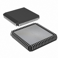
IC MCU EPROM ADC/PWM HS 68-PLCC
Manufacturer
Maxim Integrated Products
Series
87Cr
Datasheet
1.DS87C550-QNL.pdf
(49 pages)
Specifications of DS87C550-QCL+
Core Processor
8051
Core Size
8-Bit
Speed
33MHz
Connectivity
EBI/EMI, SIO, UART/USART
Peripherals
Power-Fail Reset, PWM, WDT
Number Of I /o
55
Program Memory Size
8KB (8K x 8)
Program Memory Type
OTP
Ram Size
1K x 8
Voltage - Supply (vcc/vdd)
4.5 V ~ 5.5 V
Data Converters
A/D 6x10b
Oscillator Type
External
Operating Temperature
0°C ~ 70°C
Package / Case
68-LCC, 68-PLCC
Lead Free Status / RoHS Status
Lead free / RoHS Compliant
Eeprom Size
-


Selecting a single analog signal for conversion is achieved by software writing the desired channel
number (0 through 7) into the MUX2 -MUX0 bits (ADCON2.6-4). The selected input is then provided to
a sample and hold circuit that maintains a steady signal during the conversion process.
A/D CONVERSION PROCESS
The A/D conversion process can be configured for one-shot or continuous mode operation. For one-shot
operation, the SFR bit CONT/SS (ADCON1.5) must be a 0. The conversion process is then initiated by
software writing a 1 to the STRT/BSY SFR bit (ADCON1.7) if the ADEX (ADCON1.4) bit is a 0. If the
ADEX bit is a 1, then the conversion is initiated by an active low signal on the external pin STADC
(P6.7). If continuous mode is selected (CONT/SS = 1), then the first conversion is initiated as described
above, but another conversion will be automatically started at the completion of the previous conversion.
Once initiated, the conversion process requires 16 A/D clock periods (T
dynamic nature of the converter, the A/D clock period can be no less that 1 ms and no more than 6.25 ms.
This requirement is expressed as follows:
Therefore, any single conversion time can range from 16ms (min) to 100ms (max), depending on the
selected A/D clock frequency.
The A/D clock frequency is a function of the processor’s machine cycle clock and the A/D clock’s
prescaler setting as shown by the following equation:
where N is the prescaler setting in APS3:0.
The processor’s machine cycle clock period (T
frequency multiplied by 4 (but can be affected by the CD1, CD0, and 4X/
must be set by the user to ensure that it falls within the minimum and maximum values specified above.
As an example, assume the processor’s crystal frequency is 33MHz and that the processor is running in a
standard divide-by-4 mode. This means that the period of the processors machine cycle clock, i.e., T
will be (1/33MHz)*4 or 121.2 ns. If it is assumed that the application requires the fastest possible
conversion time, then the desired T
Therefore for this example, N = 7.25. Since N must be an integer, the value of N must be 8 (rounded up
to the next integer). This results in a conversion clock T
The prescaler value must be stored in APS3-APS0 (ADCON2.3-0) to achieve the proper A/D clock.
These bits default to 0 on reset, so they must be set as desired by the processor’s initialization software.
A/D OUTPUT
There are two SFR locations that contain the result of the A/D conversion process. They are ADMSB
(most significant byte) and ADLSB (least significant byte). The ADLSB byte always contains the 8 least
significant bits of the 10-bit result. The ADMSB can be configured in two different ways through the use
of the SFR bit OUTCF (ADCON2.7). If OUTCF is a 0, then ADMSB contains the 8 most significant bits
1.0 ms £ T
T
N = (T
ACLK
= T
ACLK
MCLK
ACLK
/T
MCLK
£ 6.25 ms
* (N+1)
)-1
ACLK
is 1.0 ms. The necessary prescale value can then be calculated as:
22 of 49
MCLK
) is normally the external crystal (or oscillator)
ACLK
= 1.091 ms.
ACLK
2X
) to complete. Because of the
bits). The A/D clock period
MCLK
,
Related parts for DS87C550-QCL+
Image
Part Number
Description
Manufacturer
Datasheet
Request
R

Part Number:
Description:
IC MCU EPROM ADC/PWM HS 68-PLCC
Manufacturer:
Maxim Integrated Products
Datasheet:

Part Number:
Description:
Eprom High-speed Microcontroller With Adc And Pwm
Manufacturer:
Maxim Integrated Products, Inc.
Datasheet:

Part Number:
Description:
MAX7528KCWPMaxim Integrated Products [CMOS Dual 8-Bit Buffered Multiplying DACs]
Manufacturer:
Maxim Integrated Products
Datasheet:
Part Number:
Description:
Single +5V, fully integrated, 1.25Gbps laser diode driver.
Manufacturer:
Maxim Integrated Products
Datasheet:
Part Number:
Description:
Single +5V, fully integrated, 155Mbps laser diode driver.
Manufacturer:
Maxim Integrated Products
Datasheet:
Part Number:
Description:
VRD11/VRD10, K8 Rev F 2/3/4-Phase PWM Controllers with Integrated Dual MOSFET Drivers
Manufacturer:
Maxim Integrated Products
Datasheet:
Part Number:
Description:
Highly Integrated Level 2 SMBus Battery Chargers
Manufacturer:
Maxim Integrated Products
Datasheet:
Part Number:
Description:
Current Monitor and Accumulator with Integrated Sense Resistor; ; Temperature Range: -40°C to +85°C
Manufacturer:
Maxim Integrated Products
Part Number:
Description:
TSSOP 14/A°/RS-485 Transceivers with Integrated 100O/120O Termination Resis
Manufacturer:
Maxim Integrated Products
Part Number:
Description:
TSSOP 14/A°/RS-485 Transceivers with Integrated 100O/120O Termination Resis
Manufacturer:
Maxim Integrated Products
Part Number:
Description:
QFN 16/A°/AC-DC and DC-DC Peak-Current-Mode Converters with Integrated Step
Manufacturer:
Maxim Integrated Products
Part Number:
Description:
TDFN/A/65V, 1A, 600KHZ, SYNCHRONOUS STEP-DOWN REGULATOR WITH INTEGRATED SWI
Manufacturer:
Maxim Integrated Products
Part Number:
Description:
Integrated Temperature Controller f
Manufacturer:
Maxim Integrated Products
Part Number:
Description:
SOT23-6/I°/45MHz to 650MHz, Integrated IF VCOs with Differential Output
Manufacturer:
Maxim Integrated Products
Part Number:
Description:
SOT23-6/I°/45MHz to 650MHz, Integrated IF VCOs with Differential Output
Manufacturer:
Maxim Integrated Products