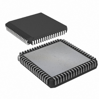
DS87C550-QCL+ Maxim Integrated Products, DS87C550-QCL+ Datasheet - Page 19

DS87C550-QCL+
Manufacturer Part Number
DS87C550-QCL+
Description
IC MCU EPROM ADC/PWM HS 68-PLCC
Manufacturer
Maxim Integrated Products
Series
87Cr
Datasheet
1.DS87C550-QNL.pdf
(49 pages)
Specifications of DS87C550-QCL+
Core Processor
8051
Core Size
8-Bit
Speed
33MHz
Connectivity
EBI/EMI, SIO, UART/USART
Peripherals
Power-Fail Reset, PWM, WDT
Number Of I /o
55
Program Memory Size
8KB (8K x 8)
Program Memory Type
OTP
Ram Size
1K x 8
Voltage - Supply (vcc/vdd)
4.5 V ~ 5.5 V
Data Converters
A/D 6x10b
Oscillator Type
External
Operating Temperature
0°C ~ 70°C
Package / Case
68-LCC, 68-PLCC
Lead Free Status / RoHS Status
Lead free / RoHS Compliant
Eeprom Size
-
DS87C550 EPROM High-Speed Microcontroller with ADC and PWM
Alternately, software can prevent an undesired exit from PMM by entering a low priority interrupt service
level before entering PMM. This will prevent other low priority interrupts from causing a Switchback.
Status also contains information about the state of the serial ports. Serial Port Zero Receive Activity
(SPRA0; STATUS.0) indicates a serial word is being received on Serial Port 0 when this bit is set to a 1.
Serial Port Zero Transmit Activity (SPTA0; STATUS.1) indicates that the serial port is still shifting out a
serial transmission. STATUS.2 (SPRA1) and STATUS.3 (SPTA1) provide the same information for
Serial Port 1, respectively. While one of these bits is set, hardware prohibits software from entering PMM
(CD1 & CD0 are write-protected) since this would corrupt the corresponding serial transmissions.
IDLE MODE
Setting the LSB of the Power Control register (PCON.0) invokes the Idle mode. Idle will leave internal
clocks, serial ports and timers running. Power consumption drops because memory is not being accessed
and instructions are not being executed. Since clocks are running, the Idle power consumption is a
function of crystal frequency. It should be approximately ½ of the operational power at a given
frequency. The CPU can exit the Idle state with any interrupt or a reset. Idle is available for backward
software compatibility. However, due to improvements over the original architecture, the processor’s
power consumption can be reduced to below Idle levels by invoking Power Management Mode (PMM)
and running NOPs.
STOP MODE
Setting bit 1 of the Power Control register (PCON.1) invokes the Stop mode. Stop mode is the lowest
power state (besides power-off) since it turns off all internal clocking. The I
of a standard Stop mode is
CC
typically 1mA (but is specified in the Electrical Specifications). All processor operation ceases at the end
of the instruction that sets PCON.1. The CPU can exit Stop mode from an external interrupt or a reset
condition. Internally generated interrupts (timer, serial port, etc.) are not useful since they require
clocking activity.
BAND-GAP SELECT
The DS87C550 provides two enhancements to the Stop mode. As described below, the DS87C550
provides a band-gap reference to determine Power-fail Interrupt and Reset thresholds. The default state is
that the band-gap reference is off while in Stop mode. This mode allows the extremely low-power state
mentioned above. A user can optionally choose to have the band-gap enabled during Stop mode. With the
band-gap reference enabled, PFI and Power-fail Reset are functional and are valid means for leaving Stop
mode. This allows software to detect and compensate for a brownout or power supply sag, even when in
Stop mode.
In Stop mode with the band-gap enabled, I
will be approximately 100mA compared with 1mA with the
CC
band-gap off. If a user does not require a Power-fail Reset or Interrupt while in Stop mode, the band-gap
can remain disabled. Only the most power-sensitive applications should turn off the band-gap, as this
results in an uncontrolled power-down condition.
The control of the band-gap reference is located in the Ring Oscillator Control Register (RCON). Setting
BGS (RCON.0) to a 1 will keep the band-gap reference enabled during Stop mode. The default or reset
condition is with the bit at a logic 0. This results in the band-gap being off during Stop mode. Note that
this bit has no control of the reference during full power, PMM, or Idle modes.
19 of 49


