YLCDRSK2378 Renesas Electronics America, YLCDRSK2378 Datasheet - Page 824
YLCDRSK2378
Manufacturer Part Number
YLCDRSK2378
Description
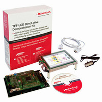
KIT DEV EVAL H8S/2378 LCD
Manufacturer
Renesas Electronics America
Series
H8®r
Datasheet
1.YR0K42378FC000BA.pdf
(1208 pages)
Specifications of YLCDRSK2378
Main Purpose
Displays, LCD Controller
Embedded
Yes, MCU, 16-Bit
Utilized Ic / Part
YLCDRSK2378
Primary Attributes
5.7" QVGA, Touch Screen
Secondary Attributes
Source Code on CD, Debugging Requires Emulator Cable E10A USB/JTAG
Lead Free Status / RoHS Status
Lead free / RoHS Compliant


Section 15 Serial Communication Interface (SCI, IrDA)
1. If an error is found when the received parity bit is checked, the PER bit in SSR is
2. The RDRF bit in SSR is not set for a frame in which an error has occurred.
3. If no error is found when the received parity bit is checked, the PER bit in SSR is not set to 1.
4. The receive operation is judged to have been completed normally, and the RDRF flag in SSR
Figure 15.30 shows a flowchart for reception. The sequence of receive operations can be
performed automatically by specifying the DTC or DMAC to be activated with an RXI interrupt
source. In a receive operation, an RXI interrupt request is generated when the RDRF flag in SSR
is set to 1. If the RXI request is designated beforehand as a DTC or DMAC activation source, the
DTC or DMAC will be activated by the RXI request, and transfer of the receive data will be
carried out. The RDRF flag is cleared to 0 automatically when data transfer is performed by the
DTC or DMAC. If an error occurs in receive mode and the ORER or PER flag is set to 1, a
transfer error interrupt (ERI) request will be generated, and so the error flag must be cleared to 0.
In the event of an error, the DTC or DMAC is not activated and receive data is skipped. Therefore,
receive data is transferred for only the specified number of bytes in the event of an error. Even
when a parity error occurs in receive mode and the PER flag is set to 1, the data that has been
received is transferred to RDR and can be read from there.
Note: For details on receive operations in block transfer mode, refer to section 15.4, Operation in
Rev.7.00 Mar. 18, 2009 page 756 of 1136
REJ09B0109-0700
automatically set to 1. If the RIE bit in SCR is set at this time, an ERI interrupt request is
generated. The PER bit in SSR should be cleared to 0 before the next parity bit is sampled.
is automatically set to 1. If the RIE bit in SCR is set at this time, an RXI interrupt request is
generated.
Asynchronous Mode.
RDRF
PER
Ds
D0 D1 D2 D3 D4 D5 D6 D7 Dp DE
Figure 15.29 Retransfer Operation in SCI Receive Mode
nth transfer frame
[2]
[1]
Ds D0 D1 D2 D3 D4 D5 D6 D7 Dp
Retransferred frame
(DE)
[4]
[3]
Ds D0 D1 D2 D3 D4
Transfer
frame n+1
Related parts for YLCDRSK2378
Image
Part Number
Description
Manufacturer
Datasheet
Request
R

Part Number:
Description:
KIT STARTER FOR M16C/29
Manufacturer:
Renesas Electronics America
Datasheet:

Part Number:
Description:
KIT STARTER FOR R8C/2D
Manufacturer:
Renesas Electronics America
Datasheet:

Part Number:
Description:
R0K33062P STARTER KIT
Manufacturer:
Renesas Electronics America
Datasheet:

Part Number:
Description:
KIT STARTER FOR R8C/23 E8A
Manufacturer:
Renesas Electronics America
Datasheet:

Part Number:
Description:
KIT STARTER FOR R8C/25
Manufacturer:
Renesas Electronics America
Datasheet:

Part Number:
Description:
KIT STARTER H8S2456 SHARPE DSPLY
Manufacturer:
Renesas Electronics America
Datasheet:

Part Number:
Description:
KIT STARTER FOR R8C38C
Manufacturer:
Renesas Electronics America
Datasheet:

Part Number:
Description:
KIT STARTER FOR R8C35C
Manufacturer:
Renesas Electronics America
Datasheet:

Part Number:
Description:
KIT STARTER FOR R8CL3AC+LCD APPS
Manufacturer:
Renesas Electronics America
Datasheet:
Part Number:
Description:
KIT STARTER FOR RX610
Manufacturer:
Renesas Electronics America
Datasheet:

Part Number:
Description:
KIT STARTER FOR R32C/118
Manufacturer:
Renesas Electronics America
Datasheet:

Part Number:
Description:
KIT DEV RSK-R8C/26-29
Manufacturer:
Renesas Electronics America
Datasheet:

Part Number:
Description:
KIT STARTER FOR SH7124
Manufacturer:
Renesas Electronics America
Datasheet:

Part Number:
Description:
KIT STARTER FOR H8SX/1622
Manufacturer:
Renesas Electronics America
Datasheet:

Part Number:
Description:
KIT DEV FOR SH7203
Manufacturer:
Renesas Electronics America
Datasheet: