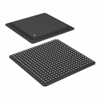
ADSP-21160MKBZ-80 Analog Devices Inc, ADSP-21160MKBZ-80 Datasheet - Page 8

ADSP-21160MKBZ-80
Manufacturer Part Number
ADSP-21160MKBZ-80
Description
32bit SHARC W/SIMD Capability
Manufacturer
Analog Devices Inc
Series
SHARC®r
Type
Floating Pointr
Specifications of ADSP-21160MKBZ-80
Interface
Host Interface, Link Port, Serial Port
Clock Rate
80MHz
Non-volatile Memory
External
On-chip Ram
512kB
Voltage - I/o
3.30V
Voltage - Core
2.50V
Operating Temperature
0°C ~ 85°C
Mounting Type
Surface Mount
Package / Case
400-BGA
Device Core Size
32b
Architecture
Enhanced Harvard
Format
Floating Point
Clock Freq (max)
80MHz
Mips
80
Device Input Clock Speed
80MHz
Ram Size
512KB
Operating Supply Voltage (typ)
2.5/3.3V
Operating Supply Voltage (min)
2.37/3.13V
Operating Supply Voltage (max)
2.63/3.47V
Operating Temp Range
0C to 85C
Operating Temperature Classification
Commercial
Mounting
Surface Mount
Pin Count
400
Package Type
BGA
Lead Free Status / RoHS Status
Lead free / RoHS Compliant
Lead Free Status / RoHS Status
Lead free / RoHS Compliant, Lead free / RoHS Compliant
Available stocks
Company
Part Number
Manufacturer
Quantity
Price
Company:
Part Number:
ADSP-21160MKBZ-80
Manufacturer:
AD
Quantity:
310
Company:
Part Number:
ADSP-21160MKBZ-80
Manufacturer:
Analog Devices Inc
Quantity:
10 000
ADSP-21160M
Also, the clearance (length, width, and height) around the
header must be considered. Leave a clearance of at least
0.15" and 0.10" around the length and width of the header,
and reserve a height clearance to attach and detach the pod
connector.
Figure 6. JTAG Target Board Connector for JTAG
Equipped Analog Devices DSP (Jumpers in Place)
As can be seen in
the header. There are the standard JTAG signals TMS,
TCK, TDI, TDO, TRST, and EMU used for emulation
purposes (via an emulator). There are also secondary JTAG
signals BTMS, BTCK, BTDI, and BTRST that are option-
ally used for board-level (boundary scan) testing.
When the emulator is not connected to this header, place
jumpers across BTMS, BTCK, BTRST, and BTDI as
shown in
correct state to allow the DSP to run free. Remove all the
jumpers when connecting the emulator to the JTAG header.
JTAG Emulator Pod Connector
Figure 8
at the 14-pin target end.
for a target board header. The keep-out area allows the pod
connector to properly seat onto the target board header.
This board area should contain no components (chips,
resistors, capacitors, etc.). The dimensions are referenced
to the center of the 0.25" square post pin.
Figure 9. JTAG Pod Connector Keep-Out Area
details the dimensions of the JTAG pod connector
Figure
7. This holds the JTAG signals in the
Figure
Figure 9
6, there are two sets of signals on
displays the keep-out area
–8–
Figure 7. JTAG Target Board Connector with No Local
Boundary Scan
Figure 8. JTAG Pod Connector Dimensions
Design-for-Emulation Circuit Information
For details on target board design issues including: single
processor connections, multiprocessor scan chains, signal
buffering, signal termination, and emulator pod logic, see
the EE-68: Analog Devices JTAG Emulation Technical
Reference on the Analog Devices website—use site search on
“EE-68” (www.analog.com). This document is updated
regularly to keep pace with improvements to emulator
support.
Additional Information
This data sheet provides a general overview of the
ADSP-21160M architecture and functionality. For detailed
information on the ADSP-2116x Family core architecture
and instruction set, refer to the ADSP-2116x SHARC DSP
Hardware Reference.
PIN FUNCTION DESCRIPTIONS
ADSP-21160M pin definitions are listed below. Inputs
identified as synchronous (S) must meet timing require-
ments with respect to CLKIN (or with respect to TCK for
TMS, TDI). Inputs identified as asynchronous (A) can be
asserted asynchronously to CLKIN (or to TCK for TRST).
REV. 0


