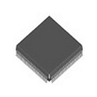
BCM5208KPF Broadcom, BCM5208KPF Datasheet - Page 13

BCM5208KPF
Manufacturer Part Number
BCM5208KPF
Description
Manufacturer
Broadcom
Datasheet
1.BCM5208KPF.pdf
(62 pages)
Specifications of BCM5208KPF
Number Of Receivers
4
Data Rate
10/100Mbps
Operating Temperature Classification
Commercial
Operating Supply Voltage (min)
3.14V
Mounting
Surface Mount
Operating Temperature (max)
70C
Operating Temperature (min)
0C
Lead Free Status / RoHS Status
Not Compliant
Available stocks
Company
Part Number
Manufacturer
Quantity
Price
Company:
Part Number:
BCM5208KPF
Manufacturer:
ON
Quantity:
201
Company:
Part Number:
BCM5208KPF
Manufacturer:
BCM
Quantity:
846
Part Number:
BCM5208KPF
Manufacturer:
BROADCOM
Quantity:
20 000
n BCM5208
November 3, 1999
FAR-END FAULT
Auto-Negotiation provides a Remote Fault capability for detection of asymmetric link failures. Since Auto-Negotiation is not
available for 100BASE-FX, the BCM5208 implements the IEEE 802.3 standard Far-End Fault mechanism for the indication
and detection of remote error conditions. If the Far-End Fault mechanism is enabled, a transceiver will transmit the Far-End
Fault Indication whenever a receive channel failure is detected (signal detect is deasserted). Each transceiver will also
continuously monitor the receive channel when a valid signal is present (signal detect asserted). When its link partner is
indicating a remote error, the transceiver will force its link monitor into the link fail state and set the Remote Fault bit in the
MII status register. The Far-End Fault mechanism is on by default in 100BASE-FX mode and off by default in 100BASE-
TX and 10BASE-T modes, and may be controlled by software after reset.
MII MANAGEMENT
Each transceiver within the BCM5208 contains an independent set of MII management registers. They share a single MDC/
MDIO serial interface, Each transceiver has a unique address and must be accessed individually. The common base
address for the group of four individual transceivers is defined by configuring the three external PHYAD address input pins.
10 MBIT SERIAL REPEATER MODE
When the 10 Mbit Serial Repeater Mode is enabled by setting SER10 high, the signal CK10RPTR is used to clock in TXD
and TXEN. Data is delivered on pin RXD(0) and taken from TXD(0). Pins RXD(3:1) and TXD(3:1) are not used.
SEGMENTATION MODE
Segmentation allows the connection of any port to any MII bus. Each transceiver has a segmentation control (Register 1Dh,
bits 14 and 15) which may be used to map it to any of the four MII busses. Segmentation, which is available only in repeater
mode, is enabled by setting bit 12 of Register 1Dh.
After segmentation is enabled, the PHY Enable bit, Register 1Dh, bit 13, must also be enabled to actually establish the
connection between the transceiver and the MII bus.
If LINK is lost and re-established at a speed different from the last speed, the PHY enable bit will automatically de-assert
in order to isolate the transceiver from the previously selected segment. The repeater controller must subsequently
determine which MII bus to attach the transceiver to before re-asserting the PHY enable bit.
INTERRUPT MODE
The BCM5208 can be programmed to provide an interrupt output from each of the four transceivers. The interrupt feature
is disabled by default. When the interrupt capability is enabled by setting MII register 1Ah, bit 14, the XMTLED# pin
becomes the INTR# pin and the RCVLED# pin becomes an “activity” pin named ACTLED#. The INTR# pins are open-drain
and may be wire-ORed together. The status of each interrupt source is also reflected in Register 1Ah, bits 1, 2 and 3. The
sources of interrupt are change in link, speed or full-duplex status. If any type of interrupt occurs, the Interrupt Status bit,
Register 1Ah, bit “0”, will be set.
In addition, each transceiver has its own register controlling the interrupt function.
If the interrupt enable bit is set to “0”, no status bits will be set and no interrupts will be generated. If the interrupt enable bit
is set to “1”, the following conditions apply:
1. If mask status bits are to “0” and the interrupt mask is set to “1”, status bits will be set but no interrupts generated.
2. If mask status bits are set to “0” and the interrupt mask is set to “0”, status bits and interrupts will be available.
3. If mask status bits are set to “1” and the interrupt mask is set to “0”, no status bits and no interrupts will be available.
Changes from “active” to “inactive” or vice versa will cause an interrupt. Setting Register 1Ah, bit 8 high will mask all
interrupts, regardless of the settings of the individual mask bits.
B r o a d c o m C o r p o r a t i o n
Document 5208-DS03-R¥¥¥¥¥
Page 5


