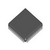
BCM5208KPF Broadcom, BCM5208KPF Datasheet - Page 41

BCM5208KPF
Manufacturer Part Number
BCM5208KPF
Description
Manufacturer
Broadcom
Datasheet
1.BCM5208KPF.pdf
(62 pages)
Specifications of BCM5208KPF
Number Of Receivers
4
Data Rate
10/100Mbps
Operating Temperature Classification
Commercial
Operating Supply Voltage (min)
3.14V
Mounting
Surface Mount
Operating Temperature (max)
70C
Operating Temperature (min)
0C
Lead Free Status / RoHS Status
Not Compliant
Available stocks
Company
Part Number
Manufacturer
Quantity
Price
Company:
Part Number:
BCM5208KPF
Manufacturer:
ON
Quantity:
201
Company:
Part Number:
BCM5208KPF
Manufacturer:
BCM
Quantity:
846
Part Number:
BCM5208KPF
Manufacturer:
BROADCOM
Quantity:
20 000
November 3, 1999
SPEED INDICATION. A read-only bit that shows the true current operation speed of the BCM5208. A “1” bit indicates
100BASE-X operation, while a “0” indicates 10BASE-T. Note that while the Auto-Negotiation exchange is performed, the
BCM5208 is always operating at 10BASE-T speed.
FULL-DUPLEX INDICATION. A read-only bit that returns a “1” when the BCM5208 is in full-duplex mode. In all other
modes, it returns a “0”.
AUXILIARY MODE REGISTER
The bit descriptions for the auxiliary mode register are shown in Table 24.
SEGMENTATION CONTROL. Applicable only when Segmentation Enable is active. These bits select which MII interface
this PHY is connected to. If RPTR=1 during reset, these bits default to “00”. If RPTR=0 during reset, these bits default to
the PHY number (00 for PHY1, etc.).
PHY ENABLE. Applicable only when Segmentation Enable is active. When set to a “1, this PHY is connected to the MII
interface specified in the Segmentation Control Register. When “0”, this PHY is disconnected from the selected MII
interface.
SEGMENTATION ENABLE. When set to a “1”, segmentation is enabled for this MII interface. When “0” this PHY connects
to its default MII interface as specified by the Segmentation Control Register’s default setting. If RPTR=1 during reset,
segmentation is enabled by default.
ACTIVITY LEDs FORCE INACTIVE. When set to “1”, the XMTLED# and RCVLED# output pins are forced into their
inactive state regardless of the mode (normal, FDX, Interrupt, or Serial) these outputs are configured to. When “0”,
XMTLED# and RCVLED# output pins are enabled.
LINK LED FORCE INACTIVE. When set to “1”, the Link LED output pin is forced into its inactive state. When “0”, Link LED
output is enabled.
Block TXEN Mode. When this mode is enabled, short IPGs of 1, 2, 3 or 4 TXC cycles will all result in the insertion of two
IDLEs before the beginning of the next packet’s JK symbols.
Document 5208-DS03-R¥¥¥¥¥
BIT
15:14
13
12
11:5
4
3
2
1
0
Note: Default is 00 for all PHYs if RPTR pin is high during reset
NAME
Segmentation Control
PHY Enable
Segmentation Enable
Reserved
Activity LEDs Force Inactive
Link LED Force Inactive
Reserved
Block TXEN Mode
Reserved
Table 24: Auxiliary Mode Register (Address 29d, 1Dh)
R/W
R/W
R/W
R/W
RO
RO
R/W
RO
B r o a d c o m C o r p o r a t i o n
DESCRIPTION
00 = connect PHY to MII I/F 1
01 = connect PHY to MII I/F 2
10 = connect PHY to MII I/F 3
11 = connect PHY to MII I/F 4
1 = PHY enabled in segmentation mode
0 = PHY disabled in segmentation mode
1 = Segmentation Enabled
0 = Segmentation Disabled
1 = Disable XMT/RCV Activity LED outputs
0 = Allow XMT/RCV Activity LED outputs
1 = Disable Link LED output
0 = Allow Link LED output
1 = Enable Block TXEN mode
0 = Disable Block TXEN mode
0 if RPTR pin is LOW
1 if RPTR pin is HIGH
DEFAULT
PHY1=00
PHY2=01
PHY3=10
PHY4=11
See Note.
0
0
0
0
0
0
0
n BCM5208
Page 33


