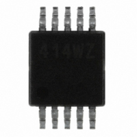
ISL22414WFU10Z Intersil, ISL22414WFU10Z Datasheet

ISL22414WFU10Z
Specifications of ISL22414WFU10Z
Available stocks
Related parts for ISL22414WFU10Z
ISL22414WFU10Z Summary of contents
Page 1
... MARKING ISL22414TFU10Z 414TZ ISL22414UFU10Z 414UZ ISL22414WFU10Z 414WZ ISL22414WMU10Z 414WM NOTES: 1. These Intersil Pb-free plastic packaged products employ special Pb-free material sets, molding compounds/die attach materials, and 100% matte tin plate plus anneal (e3 termination finish, which is RoHS compliant and compatible with both SnPb and Pb-free soldering operations). Intersil Pb-free products are MSL classified at Pb-free peak reflow temperatures that meet or exceed the Pb-free requirements of IPC/JEDEC J STD- 020 ...
Page 2
Block Diagram SCK SDO SDI INTERFACE CS Pin Descriptions MSOP PIN SYMBOL 1 SCK 2 SDO 3 SDI GND VCC 2 ISL22414 VCC POWER UP INTERFACE, SPI CONTROL ...
Page 3
... Thermal Resistance (Typical, Note 3) 10 Lead MSOP 132 +0.3 Maximum Junction Temperature (Plastic Package .+150°C CC Pb-free reflow profile . . . . . . . . . . . . . . . . . . . . . . . . . .see link below http://www.intersil.com/pbfree/Pb-FreeReflow.asp CC Recommended Operating Conditions Temperature Range Full Industrial . . . . . . . . . . . . . . . . . . . . . . . . . . . . . .-40°C to +125°C Military . . . . . . . . . . . . . . . . . . . . . . . . . . . . . . . . . . .-55°C to +125°C Power Rating . . . . . . . . . . . . . . . . . . . . . . . . . . . . . . . . . . . . .15mW V ...
Page 4
Analog Specifications Over recommended operating conditions unless otherwise stated. Boldface limits apply over the operating temperature range. (Continued) SYMBOL PARAMETER f -3dB Cut Off Frequency cutoff RESISTOR MODE (Measurements between R RINL Integral Non-linearity (Note 14) RDNL Differential Non-linearity (Note ...
Page 5
Operating Specifications Over the recommended operating conditions unless otherwise specified. Boldface limits apply over the operating temperature range. (Continued) SYMBOL PARAMETER I V- Current (Standby) V- Current (Shutdown Current (Shutdown) V-SD I Leakage Current, ...
Page 6
Operating Specifications Over the recommended operating conditions unless otherwise specified. Boldface limits apply over the operating temperature range. (Continued) SYMBOL PARAMETER R SDO Pull-up Resistor Off-chip pu (Note 17) Cpin SCK, SDI, SDO and CS Pin Capacitance f SPI Frequency ...
Page 7
DCP Macro Model R TOTAL 10pF 25pF RW Timing Diagrams Input Timing CS t LEAD SCK MSB SDI HIGH IMPEDANCE SDO Output Timing CS SCK t SO MSB SDO t V ...
Page 8
Typical Performance Curves 100 150 TAP POSITION (DECIMAL) FIGURE 1. WIPER RESISTANCE vs TAP POSITION [ I(RW FOR 10kΩ (W) CC TOTAL 0. ...
Page 9
Typical Performance Curves 0 5.5V CC 0.25 0 -0. 2.25V CC -0. 100 150 TAP POSITION (DECIMAL) FIGURE 7. DNL vs TAP POSITION IN RHEOSTAT MODE FOR 10kΩ (W) 1.60 1.20 0.80 5.5V 0.40 ...
Page 10
Typical Performance Curves SCL WIPER FIGURE 13. MIDSCALE GLITCH, CODE 7Fh TO 80h Pin Description Potentiometer Pins RH AND RL The high (RH) and low (RL) terminals of the ISL22414 are equivalent to the fixed terminals of a mechanical potentiometer. ...
Page 11
When the WR register of a DCP contains all ones (WR[7:0]= FFh), its wiper terminal (RW) is closest to its “High” terminal (RH). As the value of the WR increases from all zeroes ...
Page 12
All communication over the SPI interface is conducted by sending the MSB of each byte of data first. Protocol Conventions The SPI protocol contains Instruction Byte followed by one or more Data Bytes. A valid Instruction Byte contains instruction as ...
Page 13
CS 1 SCK RD ADDR SDI SDO Applications Information Communicating with ISL22414 Communication with ISL22414 proceeds using SPI interface through the ACR (address 10000b), IVR (address 00000b), WR (addresses 00000b) and General Purpose registers (addresses from 00001b to 01110b). The ...
Page 14
CS SCK DCP0 MOSI MISO CS SCK µC SDI SDO FIGURE 18. DAISY CHAIN CONFIGURATION CS SCK 16 CLKLS SDI SDO 0 SDO 1 SDO 2 FIGURE 19. DAISY CHAIN WRITE SEQUENCE ...
Page 15
CS SCK 16 CLKS 16 CLKS SDI RD DCP2 RD DCP1 SDO FIGURE 21. DAISY CHAIN READ SEQUENCE DCP 15 ISL22414 16 CLKS 16 CLKS NOP RD DCP0 DCP2 OUT 16 CLKS 16 CLKS NOP NOP ...
Page 16
... Accordingly, the reader is cautioned to verify that data sheets are current before placing orders. Information furnished by Intersil is believed to be accurate and reliable. However, no responsibility is assumed by Intersil or its subsidiaries for its use; nor for any infringements of patents or other rights of third parties which may result from its use ...


