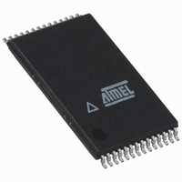
AT45DB321D-TU Atmel, AT45DB321D-TU Datasheet - Page 13

AT45DB321D-TU
Manufacturer Part Number
AT45DB321D-TU
Description
IC FLASH 32MBIT 66MHZ 28TSOP
Manufacturer
Atmel
Specifications of AT45DB321D-TU
Format - Memory
FLASH
Memory Type
DataFLASH
Memory Size
32M (8192 pages x 528 bytes)
Speed
66MHz
Interface
SPI, RapidS
Voltage - Supply
2.7 V ~ 3.6 V
Operating Temperature
-40°C ~ 85°C
Package / Case
28-TSOP
Architecture
Sectored
Interface Type
SPI
Supply Voltage (max)
3.6 V
Supply Voltage (min)
2.7 V
Maximum Operating Current
15 mA
Mounting Style
SMD/SMT
Organization
528 B x 8192
Memory Configuration
8192 Pages X 528 Bytes
Clock Frequency
20MHz
Supply Voltage Range
2.7V To 3.6V
Memory Case Style
TSOP
Rohs Compliant
Yes
Lead Free Status / RoHS Status
Lead free / RoHS Compliant
Available stocks
Company
Part Number
Manufacturer
Quantity
Price
Part Number:
AT45DB321D-TU
Manufacturer:
ATMEL/爱特梅尔
Quantity:
20 000
9. Hardware Controlled Protection
Figure 9-1.
Table 9-1.
3597O–DFLASH–10/09
Period
Time
1
2
3
WP
WP Pin
WP Pin and Protection Status
WP Pin and Protection Status
High
High
Low
Sectors specified for protection in the Sector Protection Register and the Sector Protection Reg-
ister itself can be protected from program and erase operations by asserting the WP pin and
keeping the pin in its asserted state. The Sector Protection Register and any sector specified for
protection cannot be erased or reprogrammed as long as the WP pin is asserted. In order to
modify the Sector Protection Register, the WP pin must be deasserted. If the WP pin is perma-
nently connected to GND, then the content of the Sector Protection Register cannot be changed.
If the WP pin is deasserted, or permanently connected to V
Protection Register can be modified.
The WP pin will override the software controlled protection method but only for protecting the
sectors. For example, if the sectors were not previously protected by the Enable Sector Protec-
tion command, then simply asserting the WP pin would enable the sector protection within the
maximum specified t
would no longer be enabled (after the maximum specified t
tor Protection command was not issued while the WP pin was asserted. If the Enable Sector
Protection command was issued before or while the WP pin was asserted, then simply deassert-
ing the WP pin would not disable the sector protection. In this case, the Disable Sector
Protection command would need to be issued while the WP pin is deasserted to disable the sec-
tor protection. The Disable Sector Protection command is also ignored whenever the WP pin is
asserted.
A noise filter is incorporated to help protect against spurious noise that may inadvertently assert
or deassert the WP pin.
The table below details the sector protection status for various scenarios of the WP pin, the
Enable Sector Protection command, and the Disable Sector Protection command.
Command Issued During Period 1
Command Not Issued Previously
1
Enable Sector Protection
Issue Command
Issue Command
Command
or 2
X
–
–
WPE
time. When the WP pin is deasserted; however, the sector protection
Protection Command
2
Issue Command
Issue Command
Disable Sector
Not Issued Yet
X
–
X
–
WPD
Sector Protection
CC
time) as long as the Enable Sec-
, then the content of the Sector
Disabled
Disabled
Disabled
Enabled
Enabled
Enabled
Enabled
Status
3
AT45DB321D
Read/Write
Read/Write
Read/Write
Read/Write
Read/Write
Read/Write
Protection
Read Only
Register
Sector
13


