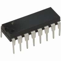
FAN4800IN Fairchild Semiconductor, FAN4800IN Datasheet - Page 12

FAN4800IN
Manufacturer Part Number
FAN4800IN
Description
IC PFC CONTROLLER CCM/DCM 16DIP
Manufacturer
Fairchild Semiconductor
Specifications of FAN4800IN
Mode
Continuous Conduction (CCM), Discontinuous Conduction (DCM)
Frequency - Switching
66kHz ~ 84kHz
Current - Startup
100µA
Voltage - Supply
11 V ~ 16.5 V
Operating Temperature
-40°C ~ 125°C
Mounting Type
Through Hole
Package / Case
16-DIP (0.300", 7.62mm)
Mounting Style
Through Hole
Lead Free Status / RoHS Status
Lead free / RoHS Compliant
Available stocks
Company
Part Number
Manufacturer
Quantity
Price
Part Number:
FAN4800IN
Manufacturer:
FSC
Quantity:
20 000
FAN4800 Rev. 1.0.5
© 2005 Fairchild Semiconductor Corporation
where:
Z
GM
V
R
2.5V:
L:
A modest degree of gain contouring is applied to the
transfer characteristic of the current error amplifier to
increase its response speed to current-loop perturba-
tions. However, the boost inductor is usually the domi-
nant factor in overall current loop response. Therefore,
this contouring is significantly less marked than that of
the voltage error amplifier. This is illustrated in Figure 8.
There is an RC filter between R
There are two reasons to add a filter at the I
1) Protection: During start-up or in-rush current condi-
2) To reduce L, the boost inductor: The I
Figure 8. Compensation Network Connection for the
CI
OUTDC
Output
S
PFC
:
:
I
tions, there is a large voltage across R
sensing resistor of the PFC boost converter. It
requires the I
can reduce the boost inductor value since the I
filter behaves like an integrator before the I
which is the input of the current error amplifier, I
:
: PFC boost output voltage (typical designed
15
2
4
3
Voltage and Current Error Amplifiers
value is 380V). The equation uses the worst-
case condition to calculate the Z
ramp.
Boost inductor.
Amplitude of the PFC leading modulation
Transconductance of I
Sensing resistor of the boost converter.
Compensation network for the current loop.
2.5V
V
I
V
I
SENSE
RMS
AC
FB
SENSE
V
EAO
Modulator
filter to attenuate the energy.
Gain
16
S
3.5k
EAO
and I
3.5k
.
SENSE
I
EAO
SENSE
CI
S
.
, which is the
V
SENSE
FAN4800 Rev.02
1
ref
pin.
PFC CMP
SENSE
filter also
SENSE
pin:
EAO
pin,
.
12
The I
the I
SET
Selecting an R
I
f
boost inductor can be reduced six times without disturb-
ing the stability. The capacitor of the I
TER
1.9 Oscillator (RAMP1)
The oscillator frequency is determined by the values of
R
oscillator output clock:
The dead time of the oscillator is derived from the follow-
ing equation:
at V
The dead time of the oscillator may be determined using:
The dead time is so small (t
ating frequency can typically be approximated by:
EAO
pfc
T
Figure 9. External Component Connection to V
/6, one sixth of the PFC switching frequency, so the
and C
, is approximately 283nF.
REF
x R
SENSE
less than 5mV. Design the pole of I
SENSE
S
= 7.5V and t
can generate an offset voltage of I
T
, which determine the ramp and off-time of the
filter is between 100Ω and 50Ω because I
t
DEAD
t
filter is an RC filter. The resistor value of
RAMP
FAN4800
FILTER
V
f
GND
O S C
V
BIAS
CC
=
=
R
C
12.11mA
BIAS
=
RAMP
T
f
equal to 50Ω keeps the offset of the
2.75
OSC
t
×
R A M P
R
T
=
V
= C
×
t
RAMP
RAMP
ln
1
+
×
1
Ceramic
T
0.22μF
⎛
⎜
⎝
C
t
V
V
D E A D
x R
T
REF
REF
>>t
FAN4800 Rev.03
=
T
-1.00
-3.75
227 C
DEAD
x 0.55.
SENSE
15V
×
Zener
⎞
⎟
⎠
) that the oper-
SENSE
T
www.fairchildsemi.com
EAO
filter, C
.
filter at
CC
(10)
OFF-
(11)
(9)
FIL-
(8)


