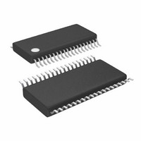
LTC3829EFE#PBF Linear Technology, LTC3829EFE#PBF Datasheet - Page 16

LTC3829EFE#PBF
Manufacturer Part Number
LTC3829EFE#PBF
Description
IC BUCK SYNC ADJ 38TSSOP
Manufacturer
Linear Technology
Type
Step-Down (Buck)r
Datasheet
1.LTC3829EFEPBF.pdf
(40 pages)
Specifications of LTC3829EFE#PBF
Internal Switch(s)
No
Synchronous Rectifier
Yes
Number Of Outputs
1
Voltage - Output
0.6 ~ 5 V
Frequency - Switching
250kHz ~ 770kHz
Voltage - Input
4.5 ~ 38 V
Operating Temperature
-40°C ~ 125°C
Mounting Type
Surface Mount
Package / Case
38-TSSOP Exposed Pad, 38-eTSSOP, 38-HTSSOP
Lead Free Status / RoHS Status
Lead free / RoHS Compliant
Current - Output
-
Power - Output
-
Available stocks
Company
Part Number
Manufacturer
Quantity
Price
LTC3829
applicaTions inForMaTion
peak sense voltage can be as low as 20mV. In addition,
inductor ripple currents greater than 50% with operation
up to 1MHz are becoming more common. Under these
conditions the voltage drop across the sense resistor’s
parasitic inductance is no longer negligible. A typical sens-
ing circuit using a discrete resistor is shown in Figure 2a.
In previous generations of controllers, a small RC filter
placed near the IC was commonly used to reduce the ef-
fects of capacitive and inductive noise coupled in the sense
traces on the PCB. A typical filter consists of two series
10Ω resistors connected to a parallel 1000pF capacitor,
TEMP COMP
OPTIONAL
NETWORK
R
NTC
R
S
R
P
LTC3829
SGND
**PLACE R1 NEXT TO INDUCTOR
Figure 2. Two Different Methods of Sensing Current
*PLACE C1 NEAR SENSE
SENSE
SENSE
ITEMP
INTV
SENSE
BOOST
PGND
(2b) Using the Inductor DCR to Sense Current
PLACED NEAR SENSE PINS
SW
V
BG
TG
CC
LTC3829
IN
FILTER COMPONENTS
+
–
SGND
–
(2a) Using a Resistor to Sense Current
PINS
SENSE
SENSE
INTV
BOOST
PGND
C
SW
V
TG
BG
CC
F
IN
+
–
R
R
F
F
+
,
R1 || R2
C1*
×
C1 =
R2
resulting in a time constant of 20ns. This same RC filter,
with minor modifications, can be used to extract the resis-
tive component of the current sense signal in the presence
of parasitic inductance. For example, Figure 3 illustrates
the voltage waveform across a 2mΩ sense resistor with
a 2010 footprint for the 1.2V/15A converter operating at
100% load. The waveform is the superposition of a purely
resistive component and a purely inductive component.
It was measured using two scope probes and waveform
math to obtain a differential measurement. Based on
additional measurements of the inductor ripple current
R1**
DCR
L
C
V
SENSE RESISTOR
PLUS PARASITIC
F
CANCELLATION
IN
• 2 • R
INDUCTANCE
R
POLE-ZERO
R
S
SENSE(EQ)
F
≤ ESL/R
ESL
INDUCTOR
L
= DCR
V
S
IN
3829 F02a
DCR
R1 + R2
R2
V
OUT
3829 F02b
V
OUT
3829f


