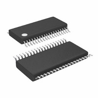
LTC3829EFE#PBF Linear Technology, LTC3829EFE#PBF Datasheet - Page 20

LTC3829EFE#PBF
Manufacturer Part Number
LTC3829EFE#PBF
Description
IC BUCK SYNC ADJ 38TSSOP
Manufacturer
Linear Technology
Type
Step-Down (Buck)r
Datasheet
1.LTC3829EFEPBF.pdf
(40 pages)
Specifications of LTC3829EFE#PBF
Internal Switch(s)
No
Synchronous Rectifier
Yes
Number Of Outputs
1
Voltage - Output
0.6 ~ 5 V
Frequency - Switching
250kHz ~ 770kHz
Voltage - Input
4.5 ~ 38 V
Operating Temperature
-40°C ~ 125°C
Mounting Type
Surface Mount
Package / Case
38-TSSOP Exposed Pad, 38-eTSSOP, 38-HTSSOP
Lead Free Status / RoHS Status
Lead free / RoHS Compliant
Current - Output
-
Power - Output
-
Available stocks
Company
Part Number
Manufacturer
Quantity
Price
LTC3829
applicaTions inForMaTion
After determining the components for the temperature
compensation network, check the results by plotting
I
equations:
where:
Use typical values for V
A will provide a minimum value for V
values are summarized in Table 1.
Table 1
The resulting current limit should be greater than or
equal to I
and 100°C.
These are typical values for the NTC compensation network:
I
0
MAX
MAX
V
SENSE(MAX)
• NTC R
• R
• R
V
V
ITE
SENSEMAX ADJ
=
versus inductor temperature using the following
I
S
P
LIM
A
M M P
DCR MAX at
≈ 20k
≈ 50k
10000
Figure 5. Resistance Versus Temperature for
the ITEMP Pin Network and the 100k NTC
1000
=
100
MAX
TYP
O
10
(
10
1
–40
= 100k, B-constant = 3000 to 4000
(
µA R
R
for inductor temperatures between 25°C
100k NTC
R
P
–20
)
R
S
)
•
= 43.2k
ITMP
= 20k
V
(
INDUCTOR TEMPERATURE (°C)
=
SENSEMAX ADJ
30mV
GND
5mV
V
25
S
0
SENSE MAX
THERMISTOR RESISTANCE
R
T
B = 4334 FOR 25°C/100°C
+
°
O
O
R
C
SENSE(MAX)
20
= 25°C
= 100k
P
•
(
(
||
1+ +
40
(
R
NTC
(
)
T
60
)
•
L MAX
)
–
(
FLOAT
1 8
50mV
5mV
.
∆
. Subtracting constant
80
V
V V
SENSE
)
–
1 3
100
–
SENSE(MAX)
.
3829 F05
25
ITEMP
120
°
/
C
3
)
• . /
–
INTV
0 4 100
75mV
7mV
A
. These
CC
)
Generating the I
first using the above values as a starting point and then
adjusting the R
approach. Figure 6 shows a typical curve of I
inductor temperature.
The same thermistor network can be used to correct for
temperatures less than 25°C. But make sure V
greater than 0.2V for duty cycles of 25% or more, oth-
erwise temperature correction may not occur at elevated
ambients. For the most accurate temperature detection,
place the thermistors next to the inductors as shown in
Figure 7. Take care to keep the ITEMP pin away from the
switch nodes.
Figure 7. Thermistor Location. Place Thermistor Next to
Inductor(s) for Accurate Sensing of the Inductor Temperature,
But Keep the ITEMP Pin Away from the Switch Nodes and Gate
Drive Traces
Figure 6. Worst-Case I
with and without NTC Temperature Compensation
V
SW1
OUT
L1
25
20
15
10
0
5
–40
R
R
NTC THERMISTOR:
R
T
B = 4334
MAX
S
P
S
O
NOMINAL
O
= 20k
= 43.2k
–20
= 25°C
= 100k
and R
I
MAX
INDUCTOR TEMPERATURE (°C)
versus inductor temperature curve plot
0
MAX
R
P
20
NTC
Versus Inductor Temperature Curve
values as necessary is another
SW2
40
L2
CORRECTED
UNCORRECTED
I
MAX
60
I
MAX
80
100
3829 F06
120
SW3
L3
MAX
ITEMP
3829 F07
versus
3829f
is


