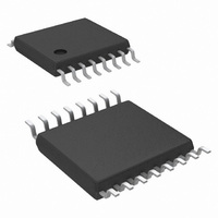
LM25088MH-1/NOPB National Semiconductor, LM25088MH-1/NOPB Datasheet - Page 13

LM25088MH-1/NOPB
Manufacturer Part Number
LM25088MH-1/NOPB
Description
IC CTLR BUCK NON-SYNC 16-TSSOP
Manufacturer
National Semiconductor
Series
PowerWise®r
Type
Step-Down (Buck)r
Datasheet
1.LM25088MH-2NOPB.pdf
(28 pages)
Specifications of LM25088MH-1/NOPB
Design Resources
LM(2)5088-1/2 QS Component Calculator
Internal Switch(s)
No
Synchronous Rectifier
No
Number Of Outputs
1
Voltage - Output
1.21 ~ 45 V
Current - Output
10A
Frequency - Switching
200kHz, 500kHz
Voltage - Input
4.5 ~ 42 V
Operating Temperature
-40°C ~ 125°C
Mounting Type
Surface Mount
Package / Case
16-TSSOP Exposed Pad, 16-eTSSOP, 16-HTSSOP
Primary Input Voltage
42V
No. Of Outputs
1
Output Voltage
1.2V
Output Current
10A
No. Of Pins
16
Operating Temperature Range
-40°C To +125°C
Msl
MSL 1 - Unlimited
Filter Terminals
SMD
Rohs Compliant
Yes
Lead Free Status / RoHS Status
Lead free / RoHS Compliant
Power - Output
-
Other names
LM25088MH-1
Available stocks
Company
Part Number
Manufacturer
Quantity
Price
Company:
Part Number:
LM25088MH-1/NOPB
Manufacturer:
NSC
Quantity:
800
Where, T
ns typical, 365 ns maximum); f
frequency and oscillator period, respectively.
From the above equation, it can be seen that for a given out-
put voltage, reducing the dropout voltage requires either re-
ducing the forced off-time or oscillator frequency (1/T
The forced off-time is limited by the time required to replenish
the bootstrap capacitor and time required to sample the re-
circulating diode current. The 365 ns forced off-time of the
LM25088 controller is a good trade-off between these two re-
quirements. Thus the LM25088 reduces dropout voltage by
dynamically decreasing the operating frequency during
dropout. The Dynamic Frequency Control (DFC) is achieved
Frequency Dithering
(LM25088-1 Only)
Electro-Magnetic Interference (EMI) emissions are funda-
mentally associated with switch-mode power supplies due to
sharp voltage transitions, diode reverse recovery currents
and the ringing of parasitic L-C circuits. These emissions will
conduct back to the power source or radiate into the environ-
ment and potentially interfering with nearby electronic sys-
tems. System designers typically use a combination of
shielding, filtering and layout techniques to reduce the EMI
emissions sufficiently to satisfy EMI emission standards es-
tablished by regulatory bodies. In a typical fixed frequency
switching converter, narrowband emissions typically peak at
the switching frequency with the successive harmonics hav-
ing less energy. Dithering the oscillator frequency spreads the
EMI energy over a range of frequencies, thus reducing the
peak levels. Dithering can also reduce the system cost by re-
ducing the size and quantity of EMI filtering components.
The LM25088-1 provides an optional frequency dithering
function which is enabled by connecting a capacitor from the
OSC
= 1/f
SW
and T
FIGURE 4. Dropout Voltage Reduction using Dynamic Frequency Control
OFF (max)
SW
and T
is the forced off-time (280
OSC
are the oscillator
OSC
).
13
using a dropout monitor, which detects a dropout condition
and reduces the operating frequency. The operating frequen-
cy will continue to decrease with decreasing input voltage until
the frequency falls to the minimum value set by the DFC cir-
cuitry.
If the VIN voltage continues to fall below this point, output
regulation can no longer be maintained. The oscillator fre-
quency will revert back to the nominal operating frequency set
by the RT resistor when the input voltage increases above the
dropout range. DFC circuitry does not affect the PWM during
normal operating conditions.
dither pin (DITH) to GND. Connecting the DITH pin directly to
GND disables frequency dithering causing the oscillator to
operate at the frequency established by the RT resistor. As
shown in Figure 5, the C
triangular wave centered at 1.2V. This triangular waveform is
used to manipulate the oscillator circuit such that the oscillator
frequency modulates from -5% to +5% of the nominal oper-
ating frequency set by the RT resistor. The C
value sets the rate of the low frequency modulation i.e., a
lower value C
quency from -5% to +5% at a faster rate than a higher value
capacitor. For the dither circuit to work effectively the modu-
lation rate must be much less than the oscillator frequency
(f
SW
) , C
dither
should be selected such that;
dither
f
SW(minDFC)
capacitor will modulate the oscillator fre-
dither
≊
1/3 x f
capacitor is used to generate a
SW(nominal)
30087610
dither
www.national.com
capacitor


