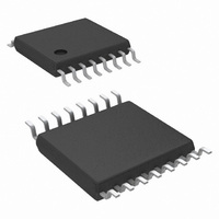
LM25088MH-1/NOPB National Semiconductor, LM25088MH-1/NOPB Datasheet - Page 17

LM25088MH-1/NOPB
Manufacturer Part Number
LM25088MH-1/NOPB
Description
IC CTLR BUCK NON-SYNC 16-TSSOP
Manufacturer
National Semiconductor
Series
PowerWise®r
Type
Step-Down (Buck)r
Datasheet
1.LM25088MH-2NOPB.pdf
(28 pages)
Specifications of LM25088MH-1/NOPB
Design Resources
LM(2)5088-1/2 QS Component Calculator
Internal Switch(s)
No
Synchronous Rectifier
No
Number Of Outputs
1
Voltage - Output
1.21 ~ 45 V
Current - Output
10A
Frequency - Switching
200kHz, 500kHz
Voltage - Input
4.5 ~ 42 V
Operating Temperature
-40°C ~ 125°C
Mounting Type
Surface Mount
Package / Case
16-TSSOP Exposed Pad, 16-eTSSOP, 16-HTSSOP
Primary Input Voltage
42V
No. Of Outputs
1
Output Voltage
1.2V
Output Current
10A
No. Of Pins
16
Operating Temperature Range
-40°C To +125°C
Msl
MSL 1 - Unlimited
Filter Terminals
SMD
Rohs Compliant
Yes
Lead Free Status / RoHS Status
Lead free / RoHS Compliant
Power - Output
-
Other names
LM25088MH-1
Available stocks
Company
Part Number
Manufacturer
Quantity
Price
Company:
Part Number:
LM25088MH-1/NOPB
Manufacturer:
NSC
Quantity:
800
The maximum ripple current occurs at the maximum input
voltage. Typically, I
the full load current. Higher ripple current will result in a small-
er inductor. However, it places more burden on the output
capacitor to smooth out the ripple current to achieve low out-
put ripple voltage. For this example 40% ripple was chosen
for a smaller sized inductor.
The nearest standard value of 6.8 µH will be used. To prevent
saturation, the inductor must be rated for the peak current.
During normal operation, the peak current occurs at maxi-
mum load current (plus maximum ripple). With properly
scaled component values, the peak current is limited to V
(TH)
voltage with a shorted output, the chosen inductor must be
evaluated at elevated temperature. It should be noted that the
saturation current rating of inductors drops significantly at el-
evated temperatures.
CURRENT SENSE RESISTOR
The current limit value (I
tor (R
R
Some ‘margin’ beyond the maximum load current is recom-
mended for the current limit threshold. In this design example,
S
/R
can be calculated by
S
S
).
During overload conditions. At the maximum input
PP
is selected between 20% and 40% of
LIM
) is set by the current sense resis-
FIGURE 9. Inductor Current
CS
17
the current limit is set at 10% above the maximum load cur-
rent, resulting in a R
should be Kelvin connected to the current sense resistor.
RAMP CAPACITOR
With the inductor and sense resistor value selected, the value
of the ramp capacitor (C
ramp circuit is given by:
Where, L is the value of the output inductor, gm is the ramp
generator transconductance (5 µA/V) and A is the current
sense amplifier gain (10V/V). For the current design example,
the ramp capacitor is calculated as:
The next lowest standard value 270 pF was selected for
C
ommended. It should be noted that selecting a capacitor value
lower than the calculated value will increase the slope com-
pensation. Furthermore, selecting a ramp capacitor substan-
tially lower or higher than the calculated value will also result
in incorrect PWM operation.
For VOUT > 5V, internal slope compensation provided by the
LM25088 may not be adequate for certain operating condi-
tions especially at low input voltages. A pull-up resistor may
be added from VCC to RAMP the pin to increase the slope
compensation. Optimal slope compensation current may be
calculated from
and R
RAMP
RAMP
. An NPO capacitor with 5% or better tolerance is rec-
is given by
S
I
OS
value of 10 mΩ. The CS and CSG pins
= V
RAMP
OUT
) necessary for the emulation
x 5 µA/V
30087618
www.national.com


