QW1 TechTools, QW1 Datasheet - Page 211
Specifications of QW1
Contents
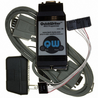
MCU Programmer with In-Circuit Serial Programming Cable and Optional GANG Adapters
For Use With/related Products
PIC Micro® MCU
For Use With
CBL-ICSP - CABLE PROG QUICKWRITER SERIALQW-4SSOP18 - ADAPTER QUICKWRITER 4GANG 18SSOPQW-4SSOP28 - ADAPTER QUICKWRITER 4GANG 28SSOPQW-4SO8/14W - ADAPT QUICKWRTR 4GANG 8/14SOIC WQW-4SO8/14N - ADAPT QUICKWRTR 4GANG 8/14SOIC NQW-4SOIC18 - ADAPTER QUICKWRITER 4GANG 18SOICQW-4ZIF18 - ADAPTER QUICKWRITER 4-GANG 18ZIFQW-4SOIC28 - ADAPTER QUICKWRITER 4GANG 28SOICQW-4PLCC44 - ADAPTER QUICKWRITER 4GANG 44PLCCQW-4ZIF40/28 - ADAPT QUICKWRITER 4GANG 40/28ZIFMP-ZIF14 - ADAPTER QUICKWRITER 14-PIN ZIFMP-SOIC8/14 - ADAPTER QUICKWRITER 8/14-SOICMP-SSOP18 - ADAPTER QUICKWRITER 18-SSOPMP-SSOP28 - ADAPTER QUICKWRITER 28-SSOPMP-14000 - ADAPTR QUICKWRTR PIC14000 28-PINMP-SOIC18 - ADAPTER QUICKWRITER 18-SOICMP-SOIC28 - ADAPTER QUICKWRITER 28-SOICMP-PLCC44 - ADAPTER QUICKWRITER 44-PIN PLCCMP-ZIF18/28 - ADAPTER QUICKWRITER 18/28PIN ZIFMP-ZIF40 - ADAPTER QUICKWRITER 40-PIN ZIF
Available stocks
Company
Part Number
Manufacturer
Quantity
Price
Company:

Part Number:
QW152
Manufacturer:
Laird Technologies IAS
Quantity:
135


© 2007 TechTools
5.8
Optional Modules
As mentioned in the hardware installation text, there are two optional modules for ClearView
Mathias; these modules are described below:
Trace Buffer Module:
This module keeps a record of each instruction executed by the emulator. For each
instruction, the record shows the location in the trace buffer memory, the value of the
program counter, the state of external trace inputs, and the original line of source code.
The trace module also provides information about how many cycles and how much time
is taken by each instruction.
The trace buffer memory is 16K "deep," resulting in a capacity of approximately 16,384
Microchip instructions. Some instructions, such as JMP and GOTO, take two processor
cycles, and therefore take two locations in the trace buffer memory. In addition, some
TechTools instructions utilize two or three Microchip instructions, and will therefore take
multiple locations in the trace buffer (this is also true of high-level compiled languages,
such as C).
On the hardware side, the trace buffer adds eight external trace inputs. The status of the
eight trace inputs is recorded along with each instruction in the trace buffer. By
connecting these inputs to your circuit, you can record the activity of your circuit as it
relates to the emulated PIC.
In addition to eight trace inputs, the trace module adds one more signal: an external
break input. This input acts like an interrupt, and may be connected to your circuit. If the
external break input transitions from high to low, then the emulator will halt execution.
Please note, however, that it takes the emulator two or three cycles to react to an external
break. This is because it takes one or two cycles to recognize the input, and another cycle
to halt the emulator (to be recognized in the first instruction cycle, the break input must be
valid at least 60ns before the start of the cycle).
The hardware inputs described above are present on the trace input header, which is
found on every PIC
member module
201
. A pin-out of this header is shown below:
ClearView Mathias Hardware
205
Related parts for QW1
Image
Part Number
Description
Manufacturer
Datasheet
Request
R

Part Number:
Description:
ADAPT QUICKWRTR 4GANG 8/14SOIC N
Manufacturer:
TechTools
Datasheet:

Part Number:
Description:
ADAPT QUICKWRTR 4GANG 8/14SOIC W
Manufacturer:
TechTools
Datasheet:


Part Number:
Description:
ADAPTER QUICKWRITER 4GANG 18SOIC
Manufacturer:
TechTools
Datasheet:

Part Number:
Description:
ADAPTER QUICKWRITER 4GANG 44PLCC
Manufacturer:
TechTools
Datasheet:

Part Number:
Description:
ADAPTER QUICKWRITER 4GANG 28SOIC
Manufacturer:
TechTools
Datasheet:


