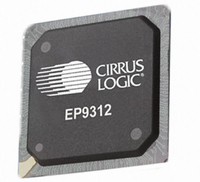
EP9312-IBZ Cirrus Logic Inc, EP9312-IBZ Datasheet - Page 515

EP9312-IBZ
Manufacturer Part Number
EP9312-IBZ
Description
IC ARM920T MCU 200MHZ 352-PBGA
Manufacturer
Cirrus Logic Inc
Series
EP9r
Specifications of EP9312-IBZ
Core Size
16/32-Bit
Package / Case
352-BGA
Core Processor
ARM9
Speed
200MHz
Connectivity
EBI/EMI, EIDE, Ethernet, I²C, IrDA, Keypad/Touchscreen, SPI, UART/USART, USB
Peripherals
AC'97, DMA, I²:S, LCD, LED, MaverickKey, POR, PWM, WDT
Number Of I /o
16
Program Memory Type
ROMless
Ram Size
32K x 8
Voltage - Supply (vcc/vdd)
1.65 V ~ 3.6 V
Data Converters
A/D 8x12b
Oscillator Type
External
Operating Temperature
-40°C ~ 85°C
Controller Family/series
(ARM9)
A/d Converter
12 Bits
No. Of I/o Pins
65
Clock Frequency
200MHz
Processor Series
EP93xx
Core
ARM920T
Data Bus Width
32 bit
3rd Party Development Tools
MDK-ARM, RL-ARM, ULINK2
Lead Free Status / RoHS Status
Lead free / RoHS Compliant
Eeprom Size
-
Program Memory Size
-
Lead Free Status / Rohs Status
Details
Other names
598-1260
Available stocks
Company
Part Number
Manufacturer
Quantity
Price
Company:
Part Number:
EP9312-IBZ
Manufacturer:
CIRRUS
Quantity:
30
Company:
Part Number:
EP9312-IBZ
Manufacturer:
HITTITE
Quantity:
1 200
- Current page: 515 of 824
- Download datasheet (13Mb)
DS785UM1
ReArbEn:
LCR:
SMEMBust:
MRS:
Initialize:
Copyright 2007 Cirrus Logic
The CKE bit must be written to ‘0’ before the ClkShutdown
bit is written to ‘1’.
Re-arbitration controller Enable - Read/Write
Writing a ‘1’ to this bit allows the SDRAM Arbiter to stop
the current burst accesses to the external synchronous
memory, allow burst accesses from another requester to
begin, and later resume the stopped burst accesses. This
can suspend burst accesses from the Raster engine long
enough to deprive the display from being adequately
refreshed, and thereby cause undesired affects to appear
on the display. So, by default, this bit is ‘0’.
Writing a ‘0’ to this bit specifies that the SDRAM Arbiter
must wait for current burst accesses to complete before it
allows burst accesses from another requester to begin.
Load FLASH Command Register - Read/Write
When Initialize = ‘0’ and MRS = ‘1’, writing a ‘1’ to this bit
allows commands to be issued to the Synchronous
FLASH device as described in
SyncFLASH Device” on page
0 - See
1 - See
Synchronous Memory Busy Status - Read/Write
This status bit shows that the Synchronous Memory
controller is either busy or idle:
0 - Idle
1 - Busy
When this bit is a ‘1’, writing a ‘1’ to it will clear it to ‘0’.
Synchronous Memory Mode Register - Read/Write
When Initialize = ‘0’ and LCR = ‘0’, writing a ‘1’ to this bit
allows setup commands to be written to the Mode register
that is inside a synchronous memory device. When this bit
is written to a ‘1’, subsequent Read accesses to the
synchronous device cause commands on the AD[13:0]
pins to be written to the Mode register.
0 - See
1 - See
Initialize bit - Read/Write
Table 13-10
Table 13-10
Table 13-14
Table 13-14
SDRAM, SyncROM, and SyncFLASH Controller
13-8:
“Programming Registers:
EP93xx User’s Guide
13-19
13
Related parts for EP9312-IBZ
Image
Part Number
Description
Manufacturer
Datasheet
Request
R

Part Number:
Description:
IC ARM9 SOC UNIVERSAL 352PBGA
Manufacturer:
Cirrus Logic Inc
Datasheet:

Part Number:
Description:
System-on-Chip Processor
Manufacturer:
Cirrus Logic Inc
Datasheet:

Part Number:
Description:
IC ARM920T MCU 200MHZ 352-PBGA
Manufacturer:
Cirrus Logic Inc
Datasheet:

Part Number:
Description:
Development Kit
Manufacturer:
Cirrus Logic Inc
Datasheet:

Part Number:
Description:
Development Kit
Manufacturer:
Cirrus Logic Inc
Datasheet:

Part Number:
Description:
High-efficiency PFC + Fluorescent Lamp Driver Reference Design
Manufacturer:
Cirrus Logic Inc
Datasheet:

Part Number:
Description:
Development Kit
Manufacturer:
Cirrus Logic Inc
Datasheet:

Part Number:
Description:
Development Kit
Manufacturer:
Cirrus Logic Inc
Datasheet:

Part Number:
Description:
Development Kit
Manufacturer:
Cirrus Logic Inc
Datasheet:

Part Number:
Description:
Development Kit
Manufacturer:
Cirrus Logic Inc
Datasheet:

Part Number:
Description:
Development Kit
Manufacturer:
Cirrus Logic Inc
Datasheet:

Part Number:
Description:
Development Kit
Manufacturer:
Cirrus Logic Inc
Datasheet:

Part Number:
Description:
Ref Bd For Speakerbar MSA & DSP Products
Manufacturer:
Cirrus Logic Inc


