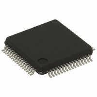
STR711FR2T6 STMicroelectronics, STR711FR2T6 Datasheet - Page 15

STR711FR2T6
Manufacturer Part Number
STR711FR2T6
Description
IC MCU ARM7 TDMI 256K 64-LQFP
Manufacturer
STMicroelectronics
Series
STR7r
Datasheet
1.RLINK-ST.pdf
(78 pages)
Specifications of STR711FR2T6
Core Processor
ARM7
Core Size
32-Bit
Speed
66MHz
Connectivity
HDLC, I²C, SmartCard, SPI, UART/USART, USB
Peripherals
PWM, WDT
Number Of I /o
30
Program Memory Size
256KB (256K x 8 + 16K)
Program Memory Type
FLASH
Ram Size
64K x 8
Voltage - Supply (vcc/vdd)
3 V ~ 3.6 V
Data Converters
A/D 4x12b
Oscillator Type
Internal
Operating Temperature
-40°C ~ 85°C
Package / Case
64-LQFP
Processor Series
STR711x
Core
ARM7TDMI
Data Bus Width
32 bit
Data Ram Size
64 KB
Interface Type
CAN/EMI/USB
Maximum Clock Frequency
66 MHz
Number Of Programmable I/os
30
Number Of Timers
4
Operating Supply Voltage
3 V to 3.6 V
Maximum Operating Temperature
+ 85 C
Mounting Style
SMD/SMT
3rd Party Development Tools
EWARM, EWARM-BL, MCBSTR7, KSK-STR711-PL, MDK-ARM, RL-ARM, ULINK2
Development Tools By Supplier
STR710-SK/HIT, STR711-SK/IAR, STR712-SK/IAR, STR71X-SK/RAIS, STX-PRO/RAIS, STX-RLINK, STR79-RVDK/CPP, STR79-RVDK, STR79-RVDK/UPG
Minimum Operating Temperature
- 40 C
On-chip Adc
4-ch x 12-bit
For Use With
MCBSTR7UME - MCBSTR7 + ULINK-ME DEV KITMCBSTR7 - BOARD EVAL STM STR71X SERIES497-5046 - KIT TOOL FOR ST7/UPSD/STR7 MCU497-4550 - KIT IAR STARTER STR711/STR712
Lead Free Status / RoHS Status
Lead free / RoHS Compliant
Eeprom Size
-
Lead Free Status / Rohs Status
Lead free / RoHS Compliant
Other names
497-4513
Available stocks
Company
Part Number
Manufacturer
Quantity
Price
Company:
Part Number:
STR711FR2T6
Manufacturer:
ST
Quantity:
74
Company:
Part Number:
STR711FR2T6
Manufacturer:
STMicroelect
Quantity:
749
Company:
Part Number:
STR711FR2T6
Manufacturer:
STMicroelectronics
Quantity:
10 000
Part Number:
STR711FR2T6
Manufacturer:
ST
Quantity:
20 000
STR71xF
Table 4.
40
41
42
43
44
45
46
47
48
49
50
51
52
53
54
55
56
57
58
Pin n°
M4 N.C.
M2 N.C.
M3 DBGRQS
M5
M6 STDBY
M7 RSTIN
H5 N.C.
H6 N.C.
G6 V
K3 V
L4
K4 CKOUT
L5
K5 RTCXTI
L6
K6 V
J4
J5
J6
V
CK
P0.15/
WAKEUP
N.C.
RTCXTO
V
N.C.
33IO-PLL
SSIO-PLL
SSBKP
18BKP
18
STR710 pin description
Pin name
I/O
O
S
S
S
I
I
I
I
C
C
C
T
Input
C
S
S
T
T
T
T
X
8mA
4mA X
Output
X
X
X
X Reset input
X Stabilization for low power voltage regulator.
X
Supply voltage for digital I/O circuitry and for PLL
reference
Not connected (not bonded)
Ground voltage for digital I/O circuitry and for PLL
reference
Not connected (not bonded)
Debug Mode request input (active high)
Clock output (f
register in APB Bridge 2
Reference clock input
Port 0.15 Wakeup from Standby mode input.
Note: This port is input only.
Not connected (not bonded)
Realtime Clock input and input of 32 kHz
oscillator amplifier circuit
Output of 32 kHz oscillator amplifier circuit
Input: Hardware Standby mode entry input active
low. Caution: External pull-up to V
select normal mode.
Output: Standby mode active low output following
Software Standby mode entry.
Note: In Standby mode all pins are in high
impedance except those marked Active in Stdby
Not connected (not bonded)
Stabilization for low power voltage regulator.
Requires external capacitors of at least 1µF
between V
Note: If the low power voltage regulator is
bypassed, this pin can be connected to an
external 1.8V supply.
Not connected (not bonded)
Not connected (not bonded)
Stabilization for main voltage regulator. Requires
external capacitors of at least 10µF + 33nF
between V
function
reset)
(after
Main
4)
18BKP
18
and V
PCLK2
and V
SS18
) Note: Enabled by CKDIS
Alternate function
SS18BKP
. See
System architecture
Figure
. See
33
Figure
5.
required to
5.
15/78


