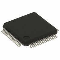
STR711FR2T6 STMicroelectronics, STR711FR2T6 Datasheet - Page 23

STR711FR2T6
Manufacturer Part Number
STR711FR2T6
Description
IC MCU ARM7 TDMI 256K 64-LQFP
Manufacturer
STMicroelectronics
Series
STR7r
Datasheet
1.RLINK-ST.pdf
(78 pages)
Specifications of STR711FR2T6
Core Processor
ARM7
Core Size
32-Bit
Speed
66MHz
Connectivity
HDLC, I²C, SmartCard, SPI, UART/USART, USB
Peripherals
PWM, WDT
Number Of I /o
30
Program Memory Size
256KB (256K x 8 + 16K)
Program Memory Type
FLASH
Ram Size
64K x 8
Voltage - Supply (vcc/vdd)
3 V ~ 3.6 V
Data Converters
A/D 4x12b
Oscillator Type
Internal
Operating Temperature
-40°C ~ 85°C
Package / Case
64-LQFP
Processor Series
STR711x
Core
ARM7TDMI
Data Bus Width
32 bit
Data Ram Size
64 KB
Interface Type
CAN/EMI/USB
Maximum Clock Frequency
66 MHz
Number Of Programmable I/os
30
Number Of Timers
4
Operating Supply Voltage
3 V to 3.6 V
Maximum Operating Temperature
+ 85 C
Mounting Style
SMD/SMT
3rd Party Development Tools
EWARM, EWARM-BL, MCBSTR7, KSK-STR711-PL, MDK-ARM, RL-ARM, ULINK2
Development Tools By Supplier
STR710-SK/HIT, STR711-SK/IAR, STR712-SK/IAR, STR71X-SK/RAIS, STX-PRO/RAIS, STX-RLINK, STR79-RVDK/CPP, STR79-RVDK, STR79-RVDK/UPG
Minimum Operating Temperature
- 40 C
On-chip Adc
4-ch x 12-bit
For Use With
MCBSTR7UME - MCBSTR7 + ULINK-ME DEV KITMCBSTR7 - BOARD EVAL STM STR71X SERIES497-5046 - KIT TOOL FOR ST7/UPSD/STR7 MCU497-4550 - KIT IAR STARTER STR711/STR712
Lead Free Status / RoHS Status
Lead free / RoHS Compliant
Eeprom Size
-
Lead Free Status / Rohs Status
Lead free / RoHS Compliant
Other names
497-4513
Available stocks
Company
Part Number
Manufacturer
Quantity
Price
Company:
Part Number:
STR711FR2T6
Manufacturer:
ST
Quantity:
74
Company:
Part Number:
STR711FR2T6
Manufacturer:
STMicroelect
Quantity:
749
Company:
Part Number:
STR711FR2T6
Manufacturer:
STMicroelectronics
Quantity:
10 000
Part Number:
STR711FR2T6
Manufacturer:
ST
Quantity:
20 000
STR71xF
Table 6.
1)
Legend / abbreviations for
Type:
In/Output level: C = CMOS 0.3V
Port and control configuration:
Input:
Output:
5V tolerant.
1
2
3
4
5
6
7
8
CANTX and CANRX in STR712F only, in STR715F they are general purpose I/Os.
VSS18
P0.10
P1.15
P0.9
P0.5
P0.2
VSS
V33
A
STR712/715 BGA Ball Connections
I = input, O = output, S = supply, HiZ= high impedance,
C
T
C/T = Programmable levels: CMOS 0.3V
pu/pd= software enabled internal pull-up or pull down
OD = open drain (logic level)
P0.11
P1.14
P0.7
P0.4
P0.1
P0.0
VSS
VSS
T
T
B
= TTL 0.8V / 2V with input trigger
= CMOS 0.3V
pu= in reset state, the internal 100kΩ weak pull-up is enabled.
pd = in reset state, the internal 100kΩ weak pull-down is enabled.
PP = push-pull
T = true OD, (P-Buffer and protection diode to V
BOOTEN
P0.12
P0.13
P1.10
P0.8
P0.3
VSS
V18
Table
C
DD
DD
7:
/0.7V
/0.7V
CANTX
P1.12/
P0.14
JTDO
P1.13
JTDI
VSS
P0.6
P1.8
DD
D
DD
1)
with input trigger
CANRX
V33IO-
P1.11/
AVDD
JTMS
P1.9
P1.7
V33
PLL
NU
E
1)
DD
V18BKP
JTRSTn
/0.7V
STDBY
VSSIO-
JTCK
P1.0
P1.6
P1.4
PLL
F
DD
or TTL 0.8V / 2V
DD
System architecture
RTCXTI
RSTIN
P0.15
AVSS
not implemented),
TEST
P1.5
P1.3
V18
G
RTCXTO
VSSBKP
VSSIO-
V33IO-
VSS18
P1.2
P1.1
PLL
PLL
CK
H
23/78


