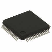
STR711FR2T6 STMicroelectronics, STR711FR2T6 Datasheet - Page 72

STR711FR2T6
Manufacturer Part Number
STR711FR2T6
Description
IC MCU ARM7 TDMI 256K 64-LQFP
Manufacturer
STMicroelectronics
Series
STR7r
Datasheet
1.RLINK-ST.pdf
(78 pages)
Specifications of STR711FR2T6
Core Processor
ARM7
Core Size
32-Bit
Speed
66MHz
Connectivity
HDLC, I²C, SmartCard, SPI, UART/USART, USB
Peripherals
PWM, WDT
Number Of I /o
30
Program Memory Size
256KB (256K x 8 + 16K)
Program Memory Type
FLASH
Ram Size
64K x 8
Voltage - Supply (vcc/vdd)
3 V ~ 3.6 V
Data Converters
A/D 4x12b
Oscillator Type
Internal
Operating Temperature
-40°C ~ 85°C
Package / Case
64-LQFP
Processor Series
STR711x
Core
ARM7TDMI
Data Bus Width
32 bit
Data Ram Size
64 KB
Interface Type
CAN/EMI/USB
Maximum Clock Frequency
66 MHz
Number Of Programmable I/os
30
Number Of Timers
4
Operating Supply Voltage
3 V to 3.6 V
Maximum Operating Temperature
+ 85 C
Mounting Style
SMD/SMT
3rd Party Development Tools
EWARM, EWARM-BL, MCBSTR7, KSK-STR711-PL, MDK-ARM, RL-ARM, ULINK2
Development Tools By Supplier
STR710-SK/HIT, STR711-SK/IAR, STR712-SK/IAR, STR71X-SK/RAIS, STX-PRO/RAIS, STX-RLINK, STR79-RVDK/CPP, STR79-RVDK, STR79-RVDK/UPG
Minimum Operating Temperature
- 40 C
On-chip Adc
4-ch x 12-bit
For Use With
MCBSTR7UME - MCBSTR7 + ULINK-ME DEV KITMCBSTR7 - BOARD EVAL STM STR71X SERIES497-5046 - KIT TOOL FOR ST7/UPSD/STR7 MCU497-4550 - KIT IAR STARTER STR711/STR712
Lead Free Status / RoHS Status
Lead free / RoHS Compliant
Eeprom Size
-
Lead Free Status / Rohs Status
Lead free / RoHS Compliant
Other names
497-4513
Available stocks
Company
Part Number
Manufacturer
Quantity
Price
Company:
Part Number:
STR711FR2T6
Manufacturer:
ST
Quantity:
74
Company:
Part Number:
STR711FR2T6
Manufacturer:
STMicroelect
Quantity:
749
Company:
Part Number:
STR711FR2T6
Manufacturer:
STMicroelectronics
Quantity:
10 000
Part Number:
STR711FR2T6
Manufacturer:
ST
Quantity:
20 000
Package characteristics
5.2
72/78
Thermal characteristics
The average chip-junction temperature, T
following equation:
Where:
●
●
●
●
P
Most of the time for the application P
may be significant if the device is configured to drive continuously external modules and/or
memories.
An approximate relationship between P
Therefore (solving equations 1 and 2):
where:
K is a constant for the particular part, which may be determined from equation (3) by
measuring P
may be obtained by solving equations (1) and (2) iteratively for any value of T
Table 44.
Symbol
I/O
Θ
Θ
Θ
Θ
JA
JA
JA
JA
represents the Power Dissipation on Input and Output Pins;
T
Θ
P
P
A
D
INT
JA
is the Ambient Temperature in °C,
is the sum of P
is the Package Junction-to-Ambient Thermal Resistance, in °C/W,
Thermal Resistance Junction-Ambient
LQFP 144 - 20 x 20 mm / 0.5 mm pitch
Thermal Resistance Junction-Ambient
LQFP 64 - 10 x 10 mm / 0.5 mm pitch
Thermal Resistance Junction-Ambient
LFBGA 64 - 8 x 8 x 1.7mm
Thermal Resistance Junction-Ambient
LFBGA 144 - 10 x 10 x 1.7mm
is the product of I
D
Thermal characteristics
(at equilibrium) for a known T
INT
K = P
and P
DD
P
T
D
J
D
and V
= T
= K / (T
x (T
Parameter
I/O
A
A
(P
+ (P
DD
I/O
+ 273°C) + Θ
D
, expressed in Watts. This is the Chip Internal Power.
< P
J
D
= P
D
+ 273°C)
J
and T
INT
, in degrees Celsius, may be calculated using the
x Θ
INT
A.
and can be neglected. On the other hand, P
JA
Using this value of K, the values of P
+ P
J
)
(if P
I/O
JA
I/O
),
x P
is neglected) is given by:
D
2
(1)
(2)
(3)
Value
42
45
58
50
A
.
STR71xF
D
and T
°C/W
°C/W
°C/W
°C/W
Unit
I/O
J


