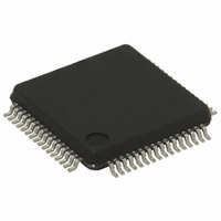
STR711FR2T6 STMicroelectronics, STR711FR2T6 Datasheet - Page 65

STR711FR2T6
Manufacturer Part Number
STR711FR2T6
Description
IC MCU ARM7 TDMI 256K 64-LQFP
Manufacturer
STMicroelectronics
Series
STR7r
Datasheet
1.RLINK-ST.pdf
(78 pages)
Specifications of STR711FR2T6
Core Processor
ARM7
Core Size
32-Bit
Speed
66MHz
Connectivity
HDLC, I²C, SmartCard, SPI, UART/USART, USB
Peripherals
PWM, WDT
Number Of I /o
30
Program Memory Size
256KB (256K x 8 + 16K)
Program Memory Type
FLASH
Ram Size
64K x 8
Voltage - Supply (vcc/vdd)
3 V ~ 3.6 V
Data Converters
A/D 4x12b
Oscillator Type
Internal
Operating Temperature
-40°C ~ 85°C
Package / Case
64-LQFP
Processor Series
STR711x
Core
ARM7TDMI
Data Bus Width
32 bit
Data Ram Size
64 KB
Interface Type
CAN/EMI/USB
Maximum Clock Frequency
66 MHz
Number Of Programmable I/os
30
Number Of Timers
4
Operating Supply Voltage
3 V to 3.6 V
Maximum Operating Temperature
+ 85 C
Mounting Style
SMD/SMT
3rd Party Development Tools
EWARM, EWARM-BL, MCBSTR7, KSK-STR711-PL, MDK-ARM, RL-ARM, ULINK2
Development Tools By Supplier
STR710-SK/HIT, STR711-SK/IAR, STR712-SK/IAR, STR71X-SK/RAIS, STX-PRO/RAIS, STX-RLINK, STR79-RVDK/CPP, STR79-RVDK, STR79-RVDK/UPG
Minimum Operating Temperature
- 40 C
On-chip Adc
4-ch x 12-bit
For Use With
MCBSTR7UME - MCBSTR7 + ULINK-ME DEV KITMCBSTR7 - BOARD EVAL STM STR71X SERIES497-5046 - KIT TOOL FOR ST7/UPSD/STR7 MCU497-4550 - KIT IAR STARTER STR711/STR712
Lead Free Status / RoHS Status
Lead free / RoHS Compliant
Eeprom Size
-
Lead Free Status / Rohs Status
Lead free / RoHS Compliant
Other names
497-4513
Available stocks
Company
Part Number
Manufacturer
Quantity
Price
Company:
Part Number:
STR711FR2T6
Manufacturer:
ST
Quantity:
74
Company:
Part Number:
STR711FR2T6
Manufacturer:
STMicroelect
Quantity:
749
Company:
Part Number:
STR711FR2T6
Manufacturer:
STMicroelectronics
Quantity:
10 000
Part Number:
STR711FR2T6
Manufacturer:
ST
Quantity:
20 000
STR71xF
4.3.10
USB characteristics
The USB interface is USB-IF certified (Full Speed).
Table 39.
Table 40.
1. All the voltages are measured from the local ground potential.
2. It is important to be aware that the DP/DM pins are not 5 V tolerant. As a consequence, in case of a a
3. R
Figure 37. USB: data signal rise and fall time
Table 41.
1. Measured from 10% to 90% of the data signal. For more detailed information, please refer to USB
Symbol
Symbol
shortcut with Vbus (typ: 5.0V), the protection diodes of the DP/DM pins will be direct biased . This will not
damage the device if not more than 50 mA is sunk for longer than 24 hours but the reliability may be
affected.
V
Specification - Chapter 7 (version 2.0).
V
V
V
V
t
V
t
Symbol
L
CRS
rfm
STARTUP
CM
OH
t
t
SE
OL
DI
r
f
is the load connected on the USB drivers
V
V
SS
Data Lines
Differential
CRS
Output signal Crossover Voltage
USB startup time
USB DC characteristics
USB: Full speed driver electrical characteristics
Differential Input Sensitivity
Differential Common Mode
Static Output Level High
Static Output Level Low
Single Ended Receiver
Rise/ Fall Time matching
USB transceiver startup time
Parameter
Threshold
Rise time
Parameter
Fall Time
Range
t
f
Parameter
Crossover
(1)
1)
points
Output Levels
Input Levels
t
r
R
R
L
Includes V
L
of 1.5 k
Conditions
of 15 k
C
C
Conditions
L
L
I(DP, DM)
=50 pF
=50 pF
t
r
Conditions
/t
f
Ω
Ω
DI
to 3.6V
to V
range
SS
(3)
(3)
Min
1.3
90
4
4
Min.
Electrical parameters
0.2
0.8
1.3
2.8
(1)(2)
Max
1
Max
110
2.0
20
20
Max.
2.0
0.3
3.6
2.5
(1)(2)
Unit
Unit
µs
ns
ns
%
V
65/78
Unit
V
V


