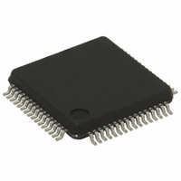
STR711FR2T6 STMicroelectronics, STR711FR2T6 Datasheet - Page 71

STR711FR2T6
Manufacturer Part Number
STR711FR2T6
Description
IC MCU ARM7 TDMI 256K 64-LQFP
Manufacturer
STMicroelectronics
Series
STR7r
Datasheet
1.RLINK-ST.pdf
(78 pages)
Specifications of STR711FR2T6
Core Processor
ARM7
Core Size
32-Bit
Speed
66MHz
Connectivity
HDLC, I²C, SmartCard, SPI, UART/USART, USB
Peripherals
PWM, WDT
Number Of I /o
30
Program Memory Size
256KB (256K x 8 + 16K)
Program Memory Type
FLASH
Ram Size
64K x 8
Voltage - Supply (vcc/vdd)
3 V ~ 3.6 V
Data Converters
A/D 4x12b
Oscillator Type
Internal
Operating Temperature
-40°C ~ 85°C
Package / Case
64-LQFP
Processor Series
STR711x
Core
ARM7TDMI
Data Bus Width
32 bit
Data Ram Size
64 KB
Interface Type
CAN/EMI/USB
Maximum Clock Frequency
66 MHz
Number Of Programmable I/os
30
Number Of Timers
4
Operating Supply Voltage
3 V to 3.6 V
Maximum Operating Temperature
+ 85 C
Mounting Style
SMD/SMT
3rd Party Development Tools
EWARM, EWARM-BL, MCBSTR7, KSK-STR711-PL, MDK-ARM, RL-ARM, ULINK2
Development Tools By Supplier
STR710-SK/HIT, STR711-SK/IAR, STR712-SK/IAR, STR71X-SK/RAIS, STX-PRO/RAIS, STX-RLINK, STR79-RVDK/CPP, STR79-RVDK, STR79-RVDK/UPG
Minimum Operating Temperature
- 40 C
On-chip Adc
4-ch x 12-bit
For Use With
MCBSTR7UME - MCBSTR7 + ULINK-ME DEV KITMCBSTR7 - BOARD EVAL STM STR71X SERIES497-5046 - KIT TOOL FOR ST7/UPSD/STR7 MCU497-4550 - KIT IAR STARTER STR711/STR712
Lead Free Status / RoHS Status
Lead free / RoHS Compliant
Eeprom Size
-
Lead Free Status / Rohs Status
Lead free / RoHS Compliant
Other names
497-4513
Available stocks
Company
Part Number
Manufacturer
Quantity
Price
Company:
Part Number:
STR711FR2T6
Manufacturer:
ST
Quantity:
74
Company:
Part Number:
STR711FR2T6
Manufacturer:
STMicroelect
Quantity:
749
Company:
Part Number:
STR711FR2T6
Manufacturer:
STMicroelectronics
Quantity:
10 000
Part Number:
STR711FR2T6
Manufacturer:
ST
Quantity:
20 000
STR71xF
Figure 42. 64-Low profile fine pitch ball grid array package
Figure 43. 144-low profile fine pitch ball grid array package
Figure 44. Recommended PCB design rules (0.80/0.75mm pitch BGA)
Dpad
Dsm
Dpad
Dsm
Solder paste
– Non solder mask defined pads are recommended
– 4 to 6 mils screen print
0.37 mm
0.52 mm typ. (depends on solder
mask registration tolerance
0.37 mm aperture diameter
Dim.
ddd
Dim.
A1
A2
D1
E1
ddd
eee
A
b
D
E
N
e
A1
A2
D1
E1
f
fff
A
D
E
N
b
e
F
1
Values in inches are converted from mm and
Package characteristics
1.210
0.270
0.450 0.500 0.550 0.018 0.020 0.022
7.750 8.000 8.150 0.305 0.315 0.321
7.750 8.000 8.150 0.305 0.315 0.321
0.720 0.800 0.880 0.028 0.031 0.035
1.050 1.200 1.350 0.041 0.047 0.053
Min
1.21
0.21
0.35 0.40 0.45 0.0138 0.0157 0.01
9.85 10.00 10.15 0.3878 0.3937 0.39
9.85 10.00 10.15 0.3878 0.3937 0.39
Min
rounded to 4 decimal digits.
1.120
5.600
5.600
mm
Typ
1.085
8.80
8.80
0.80
0.60
mm
Typ
Number of Pins
1.700 0.048
0.120
Max
Number of Pins
Max
1.70 0.0476
0.10
0.15
0.08
64
0.011
Min
0.0083
144
Min
inches
0.044
0.220
0.220
Typ
inches
0.0427
0.3465
0.3465
0.0315
0.0236
Typ
0.067
0.005
71/78
Max
1)
0.06
0.00
0.00
0.00
Ma


