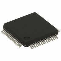
STR711FR2T6 STMicroelectronics, STR711FR2T6 Datasheet - Page 57

STR711FR2T6
Manufacturer Part Number
STR711FR2T6
Description
IC MCU ARM7 TDMI 256K 64-LQFP
Manufacturer
STMicroelectronics
Series
STR7r
Datasheet
1.RLINK-ST.pdf
(78 pages)
Specifications of STR711FR2T6
Core Processor
ARM7
Core Size
32-Bit
Speed
66MHz
Connectivity
HDLC, I²C, SmartCard, SPI, UART/USART, USB
Peripherals
PWM, WDT
Number Of I /o
30
Program Memory Size
256KB (256K x 8 + 16K)
Program Memory Type
FLASH
Ram Size
64K x 8
Voltage - Supply (vcc/vdd)
3 V ~ 3.6 V
Data Converters
A/D 4x12b
Oscillator Type
Internal
Operating Temperature
-40°C ~ 85°C
Package / Case
64-LQFP
Processor Series
STR711x
Core
ARM7TDMI
Data Bus Width
32 bit
Data Ram Size
64 KB
Interface Type
CAN/EMI/USB
Maximum Clock Frequency
66 MHz
Number Of Programmable I/os
30
Number Of Timers
4
Operating Supply Voltage
3 V to 3.6 V
Maximum Operating Temperature
+ 85 C
Mounting Style
SMD/SMT
3rd Party Development Tools
EWARM, EWARM-BL, MCBSTR7, KSK-STR711-PL, MDK-ARM, RL-ARM, ULINK2
Development Tools By Supplier
STR710-SK/HIT, STR711-SK/IAR, STR712-SK/IAR, STR71X-SK/RAIS, STX-PRO/RAIS, STX-RLINK, STR79-RVDK/CPP, STR79-RVDK, STR79-RVDK/UPG
Minimum Operating Temperature
- 40 C
On-chip Adc
4-ch x 12-bit
For Use With
MCBSTR7UME - MCBSTR7 + ULINK-ME DEV KITMCBSTR7 - BOARD EVAL STM STR71X SERIES497-5046 - KIT TOOL FOR ST7/UPSD/STR7 MCU497-4550 - KIT IAR STARTER STR711/STR712
Lead Free Status / RoHS Status
Lead free / RoHS Compliant
Eeprom Size
-
Lead Free Status / Rohs Status
Lead free / RoHS Compliant
Other names
497-4513
Available stocks
Company
Part Number
Manufacturer
Quantity
Price
Company:
Part Number:
STR711FR2T6
Manufacturer:
ST
Quantity:
74
Company:
Part Number:
STR711FR2T6
Manufacturer:
STMicroelect
Quantity:
749
Company:
Part Number:
STR711FR2T6
Manufacturer:
STMicroelectronics
Quantity:
10 000
Part Number:
STR711FR2T6
Manufacturer:
ST
Quantity:
20 000
STR71xF
Table 34.
See
1. Data based on characterisation results, not tested in production.
Table 35.
See
1. Data based on characterisation results, not tested in production.
Symbol
Symbol
t
t
t
t
t
t
t
t
t
t
t
t
WDS1
WDS2
t
t
t
WWT
WCR
WDH
RCR
t
RDS
RDH
RAH
t
WAS
WAH
RAS
RRT
RAT
WAT
RP
WP
Figure
Figure
Read to CSn Removal Time
WEn to CSn Removal Time
Write Address Setup Time
Write Address Turnaround
Read Address Setup Time
Read Address Turnaround
25,
Write Address Hold Time
29,
Read Address Hold Time
Write Data Setup Time 1
Write Data Setup Time 2
WEn Turnaround Time
EMI read operation
Read Data Setup Time
EMI write operation
RDn Turnaround Time
Write Data Hold Time
Read Data Hold Time
Write Pulse Time
Read Pulse Time
Figure
Figure
Parameter
Parameter
Time
Time
26,
30,
Figure 27
Figure 31
and
and
MCLK=50 MHz
3 wait states
50 pf load on all pins
MCLK=50 MHz
4 wait states
50 pf load on all pins
Test conditions
Test Conditions
Figure 28
Figure 32
for related timing diagrams.
for related timing diagrams.
Min
Min
77.5
1.75
0.65
1.9
0.6
20
97
77
20
27
20
19
98
22
27
20
0
1)
1)
1.5*t
1.5*t
Value
t
t
MCLK
MCLK
Typ
CLK
Value
t
t
t
Electrical parameters
t
t
MCLK
MCLK
MCLK
Typ
t
MCLK
C
C
t
t
C
C
MCLK
M
+
Max
3.25
100
21
33
21
2
Max
22.5
100
4.1
80
80
23
33
23
1)
3
1)
Unit
ns
ns
ns
ns
ns
ns
ns
ns
Unit
57/78
ns
ns
ns
ns
ns
ns
ns
ns
ns


