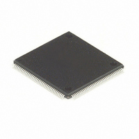
MC68HC16Z1CPV25 Freescale Semiconductor, MC68HC16Z1CPV25 Datasheet - Page 64

MC68HC16Z1CPV25
Manufacturer Part Number
MC68HC16Z1CPV25
Description
IC MPU 1K RAM 25MHZ 144-LQFP
Manufacturer
Freescale Semiconductor
Series
HC16r
Datasheet
1.MC68HC16Z1VEH16.pdf
(500 pages)
Specifications of MC68HC16Z1CPV25
Core Processor
CPU16
Core Size
16-Bit
Speed
25MHz
Connectivity
EBI/EMI, SCI, SPI
Peripherals
POR, PWM, WDT
Number Of I /o
16
Program Memory Type
ROMless
Ram Size
1K x 8
Voltage - Supply (vcc/vdd)
2.7 V ~ 5.5 V
Data Converters
A/D 8x10b
Oscillator Type
Internal
Operating Temperature
-40°C ~ 85°C
Package / Case
144-LQFP
Lead Free Status / RoHS Status
Contains lead / RoHS non-compliant
Eeprom Size
-
Program Memory Size
-
Other names
Q1141110
Available stocks
Company
Part Number
Manufacturer
Quantity
Price
Company:
Part Number:
MC68HC16Z1CPV25
Manufacturer:
MOT
Quantity:
5 510
Company:
Part Number:
MC68HC16Z1CPV25
Manufacturer:
SIEMENS
Quantity:
5 510
Company:
Part Number:
MC68HC16Z1CPV25
Manufacturer:
FREESCAL
Quantity:
624
Company:
Part Number:
MC68HC16Z1CPV25
Manufacturer:
Freescale Semiconductor
Quantity:
10 000
- Current page: 64 of 500
- Download datasheet (6Mb)
4.2.5 Condition Code Register
S — STOP Enable
MV — Accumulator M overflow flag
H — Half Carry Flag
EV — Accumulator M Extension Overflow Flag
N — Negative Flag
Z — Zero Flag
V — Overflow Flag
C — Carry Flag
IP[2:0] — Interrupt Priority Field
4-4
15
S
The 16-bit condition code register is composed of two functional blocks. The eight
MSB, which correspond to the CCR on the M68HC11, contain the low-power stop con-
trol bit and processor status flags. The eight LSB contain the interrupt priority field, the
DSP saturation mode control bit, and the program counter address extension field.
Figure 4-2
dicator and field in the register follow the figure.
MV is set when an overflow into AM35 has occurred.
H is set when a carry from A3 or B3 occurs during BCD addition.
EV is set when an overflow into AM31 has occurred.
N is set under the following conditions:
Z is set under the following conditions:
V is set when a two’s complement overflow occurs as the result of an operation.
C is set when a carry or borrow occurs during an arithmetic operation. This flag is also
used during shift and rotate to facilitate multiple word operations.
The priority value in this field (0 to 7) is used to mask interrupts.
0 = Stop clock when LPSTOP instruction is executed.
1 = Perform NOP when LPSTOP instruction is executed.
• When the MSB is set in the operand of a read operation.
• When the MSB is set in the result of a logic or arithmetic operation.
• When all bits are zero in the operand of a read operation.
• When all bits are zero in the result of a logic or arithmetic operation.
MV
14
13
H
shows the condition code register. Detailed descriptions of each status in-
EV
12
Freescale Semiconductor, Inc.
11
N
Figure 4-2 Condition Code Register
For More Information On This Product,
10
Z
CENTRAL PROCESSOR UNIT
Go to: www.freescale.com
9
V
C
8
7
IP[2:0]
6
5
SM
4
3
M68HC16 Z SERIES
USER’S MANUAL
2
PK[3:0]
1
0
Related parts for MC68HC16Z1CPV25
Image
Part Number
Description
Manufacturer
Datasheet
Request
R
Part Number:
Description:
Manufacturer:
Freescale Semiconductor, Inc
Datasheet:
Part Number:
Description:
Manufacturer:
Freescale Semiconductor, Inc
Datasheet:
Part Number:
Description:
Manufacturer:
Freescale Semiconductor, Inc
Datasheet:
Part Number:
Description:
Manufacturer:
Freescale Semiconductor, Inc
Datasheet:
Part Number:
Description:
Manufacturer:
Freescale Semiconductor, Inc
Datasheet:
Part Number:
Description:
Manufacturer:
Freescale Semiconductor, Inc
Datasheet:
Part Number:
Description:
Manufacturer:
Freescale Semiconductor, Inc
Datasheet:
Part Number:
Description:
Manufacturer:
Freescale Semiconductor, Inc
Datasheet:
Part Number:
Description:
Manufacturer:
Freescale Semiconductor, Inc
Datasheet:
Part Number:
Description:
Manufacturer:
Freescale Semiconductor, Inc
Datasheet:
Part Number:
Description:
Manufacturer:
Freescale Semiconductor, Inc
Datasheet:
Part Number:
Description:
Manufacturer:
Freescale Semiconductor, Inc
Datasheet:
Part Number:
Description:
Manufacturer:
Freescale Semiconductor, Inc
Datasheet:
Part Number:
Description:
Manufacturer:
Freescale Semiconductor, Inc
Datasheet:
Part Number:
Description:
Manufacturer:
Freescale Semiconductor, Inc
Datasheet:


