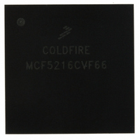
MCF5216CVF66 Freescale Semiconductor, MCF5216CVF66 Datasheet - Page 441

MCF5216CVF66
Manufacturer Part Number
MCF5216CVF66
Description
IC MPU 32BIT COLDF 256-MAPBGA
Manufacturer
Freescale Semiconductor
Series
MCF521xr
Datasheet
1.MCF5216CVM66J.pdf
(766 pages)
Specifications of MCF5216CVF66
Core Processor
Coldfire V2
Core Size
32-Bit
Speed
66MHz
Connectivity
CAN, EBI/EMI, I²C, SPI, UART/USART
Peripherals
DMA, LVD, POR, PWM, WDT
Number Of I /o
142
Program Memory Size
512KB (512K x 8)
Program Memory Type
FLASH
Ram Size
64K x 8
Voltage - Supply (vcc/vdd)
2.7 V ~ 3.6 V
Data Converters
A/D 8x12b
Oscillator Type
Internal
Operating Temperature
-40°C ~ 85°C
Package / Case
256-MAPBGA
Controller Family/series
ColdFire
Ram Memory Size
64KB
Embedded Interface Type
CAN, I2C, SPI, UART
No. Of Pwm Channels
8
Operating Temperature Range
-40°C To +85°C
No. Of Pins
256
Rohs Compliant
No
Package
256MA-BGA
Device Core
ColdFire
Family Name
MCF521x
Maximum Speed
66 MHz
Operating Supply Voltage
3.3 V
Data Bus Width
32 Bit
Number Of Programmable I/os
142
Interface Type
QSPI/UART/I2C/CAN
On-chip Adc
8-chx10-bit
Number Of Timers
8
Lead Free Status / RoHS Status
Contains lead / RoHS non-compliant
Eeprom Size
-
Available stocks
Company
Part Number
Manufacturer
Quantity
Price
Company:
Part Number:
MCF5216CVF66
Manufacturer:
FSC
Quantity:
1 670
Company:
Part Number:
MCF5216CVF66
Manufacturer:
Freescale Semiconductor
Quantity:
10 000
Part Number:
MCF5216CVF66
Manufacturer:
FREESCALE
Quantity:
20 000
Company:
Part Number:
MCF5216CVF66J
Manufacturer:
Freescale Semiconductor
Quantity:
10 000
- Current page: 441 of 766
- Download datasheet (9Mb)
framing error, overrun error, and received break conditions set the respective PE, FE, OE, and RB error
and break flags in the USRn at the received character boundary. They are valid only if USRn[RXRDY] is
set.
If a break condition is detected (URXDn is low for the entire character including the stop bit), a character
of all 0s loads into the receiver holding register and USRn[RB,RXRDY] are set. URXDn must return to a
high condition for at least one-half bit time before a search for the next start bit begins.
The receiver detects the beginning of a break in the middle of a character if the break persists through the
next character time. The receiver places the damaged character in the Rx FIFO and sets the corresponding
USRn error bits and USRn[RXRDY]. Then, if the break lasts until the next character time, the receiver
places an all-zero character into the Rx FIFO and sets USRn[RB,RXRDY].
Figure 23-20
23.4.2.3
The FIFO is used in the UART’s receive buffer logic. The FIFO consists of three receiver holding registers.
The receive buffer consists of the FIFO and a receiver shift register connected to the URXDn (see
Figure
holding register position of the FIFO. Therefore, data flowing from the receiver to the CPU is
quadruple-buffered.
In addition to the data byte, three status bits—parity error (PE), framing error (FE), and received break
(RB)—are appended to each data character in the FIFO; overrun error (OE) is not appended. By
Freescale Semiconductor
USRn[RXRDY]
USRn[FFULL]
23-18). Data is assembled in the receiver shift register and loaded into the top empty receiver
USRn[OE]
URXDn
URTSn
1
Receiver
Enabled
Overrun
Internal
UMR2n[RXRTS] = 1
module
select
FIFO
shows receiver functional timing.
1
UOP0[RTS] = 1
Manually asserted first time,
automatically negated if overrun occurs
C1
MCF5282 and MCF5216 ColdFire Microcontroller User’s Manual, Rev. 3
Status
(C1)
Data
Figure 23-20. Receiver Timing Diagram
C2
C3
C4
C5 is
lost
C5
Status
Data
(C2)
C6
Automatically asserted
when ready to receive
Status
(C3)
Data
C6, C7, and C8 is lost
Status
Data
(C4)
C7
command
Reset by
UART Modules
C8
23-21
Related parts for MCF5216CVF66
Image
Part Number
Description
Manufacturer
Datasheet
Request
R
Part Number:
Description:
Manufacturer:
Freescale Semiconductor, Inc
Datasheet:
Part Number:
Description:
Manufacturer:
Freescale Semiconductor, Inc
Datasheet:
Part Number:
Description:
Manufacturer:
Freescale Semiconductor, Inc
Datasheet:
Part Number:
Description:
Manufacturer:
Freescale Semiconductor, Inc
Datasheet:
Part Number:
Description:
Manufacturer:
Freescale Semiconductor, Inc
Datasheet:
Part Number:
Description:
Manufacturer:
Freescale Semiconductor, Inc
Datasheet:
Part Number:
Description:
Manufacturer:
Freescale Semiconductor, Inc
Datasheet:
Part Number:
Description:
Manufacturer:
Freescale Semiconductor, Inc
Datasheet:
Part Number:
Description:
Manufacturer:
Freescale Semiconductor, Inc
Datasheet:
Part Number:
Description:
Manufacturer:
Freescale Semiconductor, Inc
Datasheet:
Part Number:
Description:
Manufacturer:
Freescale Semiconductor, Inc
Datasheet:
Part Number:
Description:
Manufacturer:
Freescale Semiconductor, Inc
Datasheet:
Part Number:
Description:
Manufacturer:
Freescale Semiconductor, Inc
Datasheet:
Part Number:
Description:
Manufacturer:
Freescale Semiconductor, Inc
Datasheet:
Part Number:
Description:
Manufacturer:
Freescale Semiconductor, Inc
Datasheet:


