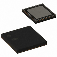
EM351-RTR Ember, EM351-RTR Datasheet - Page 131

EM351-RTR
Manufacturer Part Number
EM351-RTR
Description
IC RF TXRX ZIGBEE 128KB 48QFN
Manufacturer
Ember
Specifications of EM351-RTR
Frequency
2.4GHz
Data Rate - Maximum
250kbps
Modulation Or Protocol
802.15.4 Zigbee
Power - Output
3dBm
Sensitivity
-100dBm
Voltage - Supply
2.1 V ~ 3.6 V
Current - Receiving
26mA
Current - Transmitting
31mA
Data Interface
PCB, Surface Mount
Memory Size
128kB Flash, 12kB RAM
Antenna Connector
PCB, Surface Mount
Operating Temperature
-40°C ~ 85°C
Package / Case
48-QFN
Lead Free Status / RoHS Status
Lead free / RoHS Compliant
Applications
-
Other names
636-1010-2
Available stocks
Company
Part Number
Manufacturer
Quantity
Price
Company:
Part Number:
EM351-RTR
Manufacturer:
SILICONLABOR
Quantity:
4 550
- Current page: 131 of 245
- Download datasheet (12Mb)
When a UEV occurs, the update flag (the INT_TIMUIF bit in the INT_TIMxFLAG register) is set (unless TIM_USR
is 1) and the following registers are updated:
Figure 9-7 and Figure 9-8 show some examples of the counter behavior for different clock frequencies when
TIMx_ARR = 0x36.
9.3.2.3
In center-aligned mode, the counter counts from 0 to the auto-reload value (contents of the TIMx_ARR
register) – 1 and generates a counter overflow event, then counts from the autoreload value down to 1 and
generates a counter underflow event. Then it restarts counting from 0.
In this mode, the direction bit (TIM_DIR in the TIMx_CR1 register) cannot be written. It is updated by hardware
and gives the current direction of the counter.
The UEV can be generated at each counter overflow and at each counter underflow. Setting the TIM_UG bit in
the TIMx_EGR register by software or by using the slave mode controller also generates a UEV. In this case,
the both the counter and the prescaler’s counter restart counting from 0.
Software can disable the UEV by setting the TIM_UDIS bit in the TIMx_CR1 register. This avoids updating the
shadow registers while writing new values in the buffer registers. Then no UEV occurs until the TIM_UDIS bit
has been written to 0. However, the counter continues counting up and down, based on the current auto-
reload value.
The prescaler shadow register is reloaded with the buffer value (contents of the TIMx_PSC register).
The auto-reload active register is updated with the buffer value (contents of the TIMx_ARR register). The
auto-reload is updated before the counter is reloaded, so that the next period is the expected one.
Center-Aligned Mode (Up/Down Counting)
Figure 9-7. Counter Timing Diagram, Internal Clock Divided by 1
Figure 9-8. Counter Timing Diagram, Internal Clock Divided by 4
Final
9-7
120-035X-000G
Related parts for EM351-RTR
Image
Part Number
Description
Manufacturer
Datasheet
Request
R

Part Number:
Description:
MODULE EM351 NO PA/LNA W/ANT TG
Manufacturer:
Ember
Datasheet:

Part Number:
Description:
MODULE EM351 NO PA/LNA W/RF CONN
Manufacturer:
Ember
Datasheet:

Part Number:
Description:
MODULE EM351 PA/LNA W/ANT TG
Manufacturer:
Ember
Datasheet:

Part Number:
Description:
MODULE EM351 PA/LNA W/RF CONN
Manufacturer:
Ember
Datasheet:

Part Number:
Description:
KIT DEV EMBER ZIGBEE W/PCWH
Manufacturer:
Custom Computer Services Inc (CCS)

Part Number:
Description:
PROGRAMMER USB FLASH EM250/260
Manufacturer:
Ember
Datasheet:

Part Number:
Description:
IC ZIGBEE SYSTEM-ON-CHIP 40-QFN
Manufacturer:
Ember
Datasheet:

Part Number:
Description:
IC ZIGBEE SYSTEM-ON-CHIP 48-QFN
Manufacturer:
Ember
Datasheet:

Part Number:
Description:
IC RF TXRX ZIGBEE 192KB 48QFN
Manufacturer:
Ember
Datasheet:

Part Number:
Description:
INSIGHT ADAPTER FOR EM2XX
Manufacturer:
Ember
Datasheet:

Part Number:
Description:
IAR EWARM LICENCE FOR EM35X
Manufacturer:
Ember
Datasheet:

Part Number:
Description:
PROGRAMMER USB FLASH EM250/260
Manufacturer:
Ember
Datasheet:

Part Number:
Description:
IC ZIGBEE SYSTEM-ON-CHIP 40-QFN
Manufacturer:
Ember
Datasheet:

Part Number:
Description:
IC ZIGBEE SYSTEM-ON-CHIP 48-QFN
Manufacturer:
Ember
Datasheet:

Part Number:
Description:
IC RF TXRX ZIGBEE 192KB 48QFN
Manufacturer:
Ember
Datasheet:


