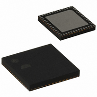
EM351-RTR Ember, EM351-RTR Datasheet - Page 164

EM351-RTR
Manufacturer Part Number
EM351-RTR
Description
IC RF TXRX ZIGBEE 128KB 48QFN
Manufacturer
Ember
Specifications of EM351-RTR
Frequency
2.4GHz
Data Rate - Maximum
250kbps
Modulation Or Protocol
802.15.4 Zigbee
Power - Output
3dBm
Sensitivity
-100dBm
Voltage - Supply
2.1 V ~ 3.6 V
Current - Receiving
26mA
Current - Transmitting
31mA
Data Interface
PCB, Surface Mount
Memory Size
128kB Flash, 12kB RAM
Antenna Connector
PCB, Surface Mount
Operating Temperature
-40°C ~ 85°C
Package / Case
48-QFN
Lead Free Status / RoHS Status
Lead free / RoHS Compliant
Applications
-
Other names
636-1010-2
Available stocks
Company
Part Number
Manufacturer
Quantity
Price
Company:
Part Number:
EM351-RTR
Manufacturer:
SILICONLABOR
Quantity:
4 550
- Current page: 164 of 245
- Download datasheet (12Mb)
TIMx_CCMR2
TIM1_CCMR2
Timer 1 Capture/Compare Mode Register 2
TIM2_CCMR2
Timer 2 Capture/Compare Mode Register 2
Timer channels can be programmed as inputs (capture mode) or outputs (compare mode). The direction of channel y is defined by TIM_CCyS in this
register.
The other bits in this register have different functions in input and in output modes. The TIM_OC* fields only apply to a channel configured as an
output (TIM_CCyS = 0), and the TIM_IC* fields only apply to a channel configured as an input (TIM_CCyS > 0).
Bitname
TIM_OC4M
TIM_OC4BE
31
23
15
0
0
0
7
0
30
22
14
6
0
0
Bitfield
[14:12]
TIM_IC4F
TIM_IC3F
[11]
TIM_OC4M
TIM_OC3M
29
21
13
0
0
5
Access
RW
RW
Description
Output Compare 4 Mode. (Applies only if TIM_CC4S = 0.)
Define the behavior of the output reference signal OC4REF from which OC4 derives.
OC4REF is active high whereas OC4’s active level depends on the TIM_CC4P bit.
000: Frozen - The comparison between the output compare register TIMx_CCR4 and the
counter TIMx_CNT has no effect on the outputs.
001: Set OC4REF to active on match. The OC4REF signal is forced high when the counter
TIMx_CNT matches the capture/compare register 4 (TIMx_CCR4)
010: Set OC4REF to inactive on match. OC4REF signal is forced low when the counter
TIMx_CNT matches the capture/compare register 4 (TIMx_CCR4).
011: Toggle - OC4REF toggles when TIMx_CNT = TIMx_CCR4.
100: Force OC4REF inactive.
101: Force OC4REF active.
110: PWM mode 1 - In up-counting, OC4REF is active as long as TIMx_CNT < TIMx_CCR4,
otherwise OC4REF is inactive. In down-counting, OC4REF is inactive if
TIMx_CNT > TIMx_CCR4, otherwise OC4REF is active.
111: PWM mode 2 - In up-counting, OC4REF is inactive if TIMx_CNT < TIMx_CCR4,
otherwise OC4REF is active. In down-counting, OC4REF is active if TIMx_CNT > TIMx_CCR4,
otherwise it is inactive.
Note: In PWM mode 1 or 2, the OC4REF level changes only when the result of the
comparison changes or when the output compare mode switches from “frozen” mode to
“PWM” mode.
Output Compare 4 Buffer Enable. (Applies only if TIM_CC4S = 0.)
0: Buffer register for TIMx_CCR4 is disabled. TIMx_CCR4 can be written at anytime, the
new value is used by the shadow register immediately.
1: Buffer register for TIMx_CCR4 is enabled. Read/write operations access the buffer
register. TIMx_CCR4 buffer value is loaded in the shadow register at each UEV.
Note: The PWM mode can be used without enabling the buffer register only in one pulse
mode (TIM_OPM bit set in the TIMx_CR2 register), otherwise the behavior is undefined.
28
20
12
0
0
4
Final
9-40
TIM_OC4BE
TIM_OC3BE
27
19
11
3
0
0
TIM_IC4PSC
TIM_IC3PSC
TIM_OC4FE
TIM_OC3FE
26
18
10
0
0
2
Address: 0x4000E01C Reset: 0x0
Address: 0x4000F01C Reset: 0x0
25
17
0
0
9
1
TIM_CC4S
TIM_CC3S
120-035X-000G
24
16
8
0
0
0
Related parts for EM351-RTR
Image
Part Number
Description
Manufacturer
Datasheet
Request
R

Part Number:
Description:
MODULE EM351 NO PA/LNA W/ANT TG
Manufacturer:
Ember
Datasheet:

Part Number:
Description:
MODULE EM351 NO PA/LNA W/RF CONN
Manufacturer:
Ember
Datasheet:

Part Number:
Description:
MODULE EM351 PA/LNA W/ANT TG
Manufacturer:
Ember
Datasheet:

Part Number:
Description:
MODULE EM351 PA/LNA W/RF CONN
Manufacturer:
Ember
Datasheet:

Part Number:
Description:
KIT DEV EMBER ZIGBEE W/PCWH
Manufacturer:
Custom Computer Services Inc (CCS)

Part Number:
Description:
PROGRAMMER USB FLASH EM250/260
Manufacturer:
Ember
Datasheet:

Part Number:
Description:
IC ZIGBEE SYSTEM-ON-CHIP 40-QFN
Manufacturer:
Ember
Datasheet:

Part Number:
Description:
IC ZIGBEE SYSTEM-ON-CHIP 48-QFN
Manufacturer:
Ember
Datasheet:

Part Number:
Description:
IC RF TXRX ZIGBEE 192KB 48QFN
Manufacturer:
Ember
Datasheet:

Part Number:
Description:
INSIGHT ADAPTER FOR EM2XX
Manufacturer:
Ember
Datasheet:

Part Number:
Description:
IAR EWARM LICENCE FOR EM35X
Manufacturer:
Ember
Datasheet:

Part Number:
Description:
PROGRAMMER USB FLASH EM250/260
Manufacturer:
Ember
Datasheet:

Part Number:
Description:
IC ZIGBEE SYSTEM-ON-CHIP 40-QFN
Manufacturer:
Ember
Datasheet:

Part Number:
Description:
IC ZIGBEE SYSTEM-ON-CHIP 48-QFN
Manufacturer:
Ember
Datasheet:

Part Number:
Description:
IC RF TXRX ZIGBEE 192KB 48QFN
Manufacturer:
Ember
Datasheet:


