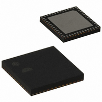
EM351-RTR Ember, EM351-RTR Datasheet - Page 134

EM351-RTR
Manufacturer Part Number
EM351-RTR
Description
IC RF TXRX ZIGBEE 128KB 48QFN
Manufacturer
Ember
Specifications of EM351-RTR
Frequency
2.4GHz
Data Rate - Maximum
250kbps
Modulation Or Protocol
802.15.4 Zigbee
Power - Output
3dBm
Sensitivity
-100dBm
Voltage - Supply
2.1 V ~ 3.6 V
Current - Receiving
26mA
Current - Transmitting
31mA
Data Interface
PCB, Surface Mount
Memory Size
128kB Flash, 12kB RAM
Antenna Connector
PCB, Surface Mount
Operating Temperature
-40°C ~ 85°C
Package / Case
48-QFN
Lead Free Status / RoHS Status
Lead free / RoHS Compliant
Applications
-
Other names
636-1010-2
Available stocks
Company
Part Number
Manufacturer
Quantity
Price
Company:
Part Number:
EM351-RTR
Manufacturer:
SILICONLABOR
Quantity:
4 550
- Current page: 134 of 245
- Download datasheet (12Mb)
For example, to configure the up-counter to count in response to a rising edge on the TI2 input, use the
following procedure:
When a rising edge occurs on TI2, the counter counts once and the INT_TIMTIF flag is set. The delay between
the rising edge on TI2 and the actual clock of the counter is due to the resynchronization circuit on the TI2
input. The relationship between rising edges on TI2 and the resulting counter clocks is shown in Figure 9-14.
9.3.3.3
This mode is selected by writing TIM_ECE = 1 in the TIMx_SMCR register. The counter can count at each rising
or falling edge on the external trigger input ETR.
The TIM_EXTRIGSEL bits in the TIMx_OR register select a clock signal that drives ETR, as shown in Table 9-2.
Configure channel 2 to detect rising edges on the TI2 input: Write TIM_CC2S = 01 in the TIMx_CCMR1
register.
Configure the input filter duration: Write the TIM_IC2F bits in the TIMx_CCMR1 register (if no filter is
needed, keep TIM_IC2F = 0000).
Note: The capture prescaler is not used for triggering, so it does not need to be configured.
Select rising edge polarity: Write TIM_CC2P = 0 in the TIMx_CCER register.
Configure the timer in external clock mode 1: Write TIM_SMS = 111 in the TIMx_SMCR register.
Select TI2 as the input source: Write TIM_TS = 110 in the TIMx_SMCR register.
Enable the counter: Write TIM_CEN = 1 in the TIMx_CR1 register.
External Clock Source Mode 2
Figure 9-14. Control Circuit in External Clock Mode 1
Figure 9-13. TI2 External Clock Connection Example
Final
9-10
120-035X-000G
Related parts for EM351-RTR
Image
Part Number
Description
Manufacturer
Datasheet
Request
R

Part Number:
Description:
MODULE EM351 NO PA/LNA W/ANT TG
Manufacturer:
Ember
Datasheet:

Part Number:
Description:
MODULE EM351 NO PA/LNA W/RF CONN
Manufacturer:
Ember
Datasheet:

Part Number:
Description:
MODULE EM351 PA/LNA W/ANT TG
Manufacturer:
Ember
Datasheet:

Part Number:
Description:
MODULE EM351 PA/LNA W/RF CONN
Manufacturer:
Ember
Datasheet:

Part Number:
Description:
KIT DEV EMBER ZIGBEE W/PCWH
Manufacturer:
Custom Computer Services Inc (CCS)

Part Number:
Description:
PROGRAMMER USB FLASH EM250/260
Manufacturer:
Ember
Datasheet:

Part Number:
Description:
IC ZIGBEE SYSTEM-ON-CHIP 40-QFN
Manufacturer:
Ember
Datasheet:

Part Number:
Description:
IC ZIGBEE SYSTEM-ON-CHIP 48-QFN
Manufacturer:
Ember
Datasheet:

Part Number:
Description:
IC RF TXRX ZIGBEE 192KB 48QFN
Manufacturer:
Ember
Datasheet:

Part Number:
Description:
INSIGHT ADAPTER FOR EM2XX
Manufacturer:
Ember
Datasheet:

Part Number:
Description:
IAR EWARM LICENCE FOR EM35X
Manufacturer:
Ember
Datasheet:

Part Number:
Description:
PROGRAMMER USB FLASH EM250/260
Manufacturer:
Ember
Datasheet:

Part Number:
Description:
IC ZIGBEE SYSTEM-ON-CHIP 40-QFN
Manufacturer:
Ember
Datasheet:

Part Number:
Description:
IC ZIGBEE SYSTEM-ON-CHIP 48-QFN
Manufacturer:
Ember
Datasheet:

Part Number:
Description:
IC RF TXRX ZIGBEE 192KB 48QFN
Manufacturer:
Ember
Datasheet:


