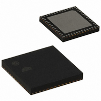
EM351-RTR Ember, EM351-RTR Datasheet - Page 93

EM351-RTR
Manufacturer Part Number
EM351-RTR
Description
IC RF TXRX ZIGBEE 128KB 48QFN
Manufacturer
Ember
Specifications of EM351-RTR
Frequency
2.4GHz
Data Rate - Maximum
250kbps
Modulation Or Protocol
802.15.4 Zigbee
Power - Output
3dBm
Sensitivity
-100dBm
Voltage - Supply
2.1 V ~ 3.6 V
Current - Receiving
26mA
Current - Transmitting
31mA
Data Interface
PCB, Surface Mount
Memory Size
128kB Flash, 12kB RAM
Antenna Connector
PCB, Surface Mount
Operating Temperature
-40°C ~ 85°C
Package / Case
48-QFN
Lead Free Status / RoHS Status
Lead free / RoHS Compliant
Applications
-
Other names
636-1010-2
Available stocks
Company
Part Number
Manufacturer
Quantity
Price
Company:
Part Number:
EM351-RTR
Manufacturer:
SILICONLABOR
Quantity:
4 550
- Current page: 93 of 245
- Download datasheet (12Mb)
8.5
TWI - Two Wire serial Interfaces
8.4.6
Refer to Registers (in the SPI Master Mode section) for a description of the SCx_DATA, SCx_SPICFG, and
SCx_SPISTAT registers.
Both EM35x serial controllers SC1 and SC2 include a Two Wire serial Interface (TWI) master controller with the
following features:
8.5.1
The TWI master controller uses just two signals:
Table 8-7 lists the GPIO pins used by the SC1 and SC2 TWI master controllers. Because the pins are configured
as open-drain outputs, they require external pull-up resistors.
8.5.2
The TWI controller is enabled by writing 3 to the SCx_MODE register. The TWI controller operates only in
master mode and supports both Standard (100 kbps) and Fast (400 kbps) TWI modes. Address arbitration is not
implemented, so multiple master applications are not supported.
The TWI master controller’s serial clock (SCL) is produced by a programmable clock generator. SCL is
produced by dividing down 12 MHz according to this equation:
Uses only two bidirectional GPIO pins
Programmable clock frequency (up to 400 kHz)
Supports both 7-bit and 10-bit addressing
Compatible with Philips’ I
SDA (Serial Data) – bidirectional serial data
SCL (Serial Clock) – bidirectional serial clock
GPIO Configuration
Registers
GPIO Usage
Set Up and Configuration
Direction
SC1 pin
SC2 pin
rate
2
C-bus slave devices
=
(
LIN
Table 8-7. TWI Master GPIO Usage
12
+
Final
8-18
MHz
1
* )
Alternate Output
Input / Output
2
(open drain)
EXP
SDA
PA1
PB1
EM351 / EM357
Alternate Output
Input / Output
(open drain)
SCL
PB2
PA2
120-035X-000G
Related parts for EM351-RTR
Image
Part Number
Description
Manufacturer
Datasheet
Request
R

Part Number:
Description:
MODULE EM351 NO PA/LNA W/ANT TG
Manufacturer:
Ember
Datasheet:

Part Number:
Description:
MODULE EM351 NO PA/LNA W/RF CONN
Manufacturer:
Ember
Datasheet:

Part Number:
Description:
MODULE EM351 PA/LNA W/ANT TG
Manufacturer:
Ember
Datasheet:

Part Number:
Description:
MODULE EM351 PA/LNA W/RF CONN
Manufacturer:
Ember
Datasheet:

Part Number:
Description:
KIT DEV EMBER ZIGBEE W/PCWH
Manufacturer:
Custom Computer Services Inc (CCS)

Part Number:
Description:
PROGRAMMER USB FLASH EM250/260
Manufacturer:
Ember
Datasheet:

Part Number:
Description:
IC ZIGBEE SYSTEM-ON-CHIP 40-QFN
Manufacturer:
Ember
Datasheet:

Part Number:
Description:
IC ZIGBEE SYSTEM-ON-CHIP 48-QFN
Manufacturer:
Ember
Datasheet:

Part Number:
Description:
IC RF TXRX ZIGBEE 192KB 48QFN
Manufacturer:
Ember
Datasheet:

Part Number:
Description:
INSIGHT ADAPTER FOR EM2XX
Manufacturer:
Ember
Datasheet:

Part Number:
Description:
IAR EWARM LICENCE FOR EM35X
Manufacturer:
Ember
Datasheet:

Part Number:
Description:
PROGRAMMER USB FLASH EM250/260
Manufacturer:
Ember
Datasheet:

Part Number:
Description:
IC ZIGBEE SYSTEM-ON-CHIP 40-QFN
Manufacturer:
Ember
Datasheet:

Part Number:
Description:
IC ZIGBEE SYSTEM-ON-CHIP 48-QFN
Manufacturer:
Ember
Datasheet:

Part Number:
Description:
IC RF TXRX ZIGBEE 192KB 48QFN
Manufacturer:
Ember
Datasheet:


